
Recess-and-protrusion-formed body

a technology of forming body and bending body, which is applied in the direction of manufacturing tools, welding/soldering/cutting articles, printing, etc., and can solve problems such as difficult elimination

Inactive Publication Date: 2018-02-15
KK TOKAI RIKA DENKI SEISAKUSHO
View PDF2 Cites 0 Cited by
  • Summary
  • Abstract
  • Description
  • Claims
  • Application Information

AI Technical Summary

Benefits of technology

The present invention relates to a recess-and-protrusion-formed body. The invention provides a method for forming the body by cooling the resin body during the laser irradiation. This method prevents ignition of the resin body and allows for larger recesses and protrusions. The technical effect of this invention is to improve the precision and quality of the recess-and-protrusion-formed body.

Problems solved by technology

In such a case, even were one recess-and-protrusion set to be formed before forming the other recess-and-protrusion set, when forming the other recess-and-protrusion set, it would be difficult to eliminate the protrusions of the one recess-and-protrusion set at a portion intersecting with the one recess-and-protrusion set.

Method used


Image

  • Recess-and-protrusion-formed body
  • Recess-and-protrusion-formed body
  • Recess-and-protrusion-formed body

Examples


Embodiment Construction

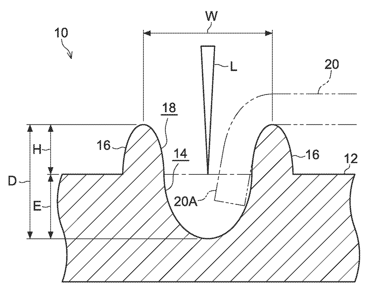
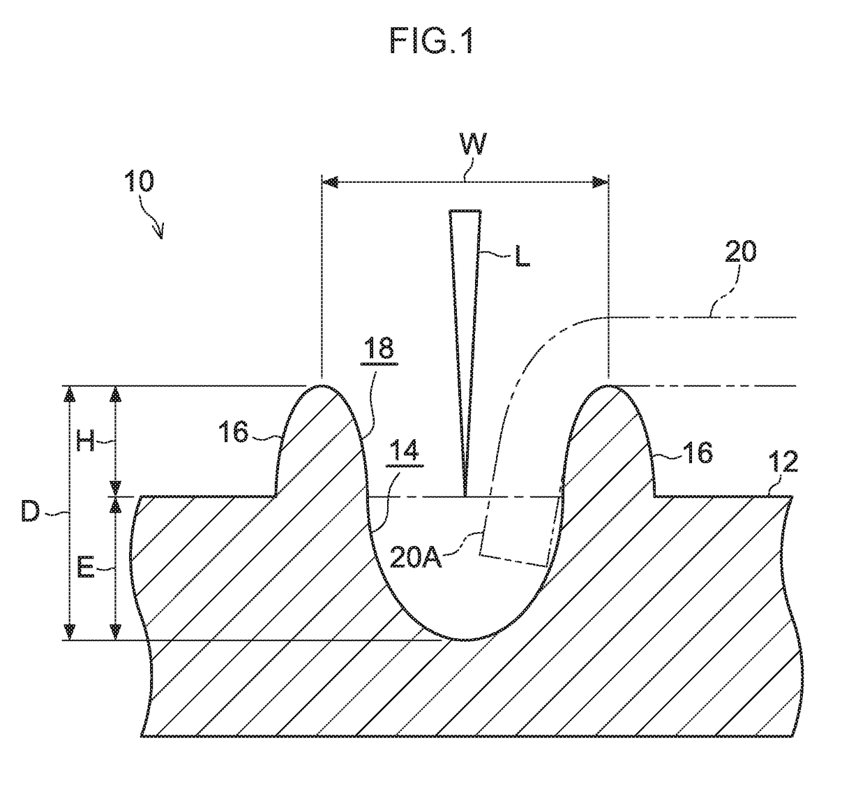
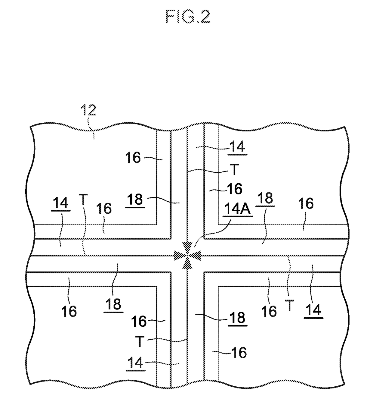
[0018]FIG. 1 is a cross-section illustrating a groove-formed body 10 (a recess-and-protrusion-formed body) according to an exemplary embodiment of the present invention. FIG. 2 is a plan view illustrating the groove-formed body 10.

[0019]The groove-formed body 10 according to the present exemplary embodiment is, for example, configured as a wheel cap, this being a vehicle component. The groove-formed body 10 is attached to a vehicle width direction outside of a wheel of a vehicle (not illustrated in the drawings).

[0020]As illustrated in FIG. 1 and FIG. 2, the groove-formed body 10 includes a plate shaped resin plate 12 serving as a resin body. The resin plate 12 is configured by, for example, a PP resin, a PC resin, an ABS resin, a PC-ABS resin, or a PA resin. The resin plate 12 has thermoplastic properties. The resin plate 12 is set with a large thickness dimension of, for example, 1.5 mm, such that the resin plate 12 has high rigidity and also has high strength against cracking, be...


PUM

PropertyMeasurementUnit
thicknessaaaaaaaaaa
diameteraaaaaaaaaa
diameteraaaaaaaaaa

Abstract

In a groove-formed body, recesses and protrusions are formed in a resin plate by irradiating a laser. Each of four recesses extend from an intersection point thereof. When forming each of the recesses in the resin plate, a portion at the intersection point of the recesses is an irradiation stop position of the laser, and an amount of heat generated by the laser on the resin plate is decreased. This enables a protrusion to be suppressed from being formed on either side of the intersection point of the recesses, and enables a protrusion to be suppressed from being disposed between the portion of the recesses at the intersection point, and a portion other than at the intersection point.

Description

TECHNICAL FIELD[0001]The present invention relates to a recess-and-protrusion-formed body in which a protrusion is disposed at the side of a recess.BACKGROUND ART[0002]In a packaging material described by Japanese Patent Application Laid-Open (JP-A) No. H10-287361, a recess is formed in a molecular-oriented thermoplastic resin layer and protrusions are formed at the sides of the recess by irradiating a laser onto the molecular-oriented thermoplastic resin layer.[0003]In this packaging material, suppose two recess-and-protrusion sets were to be formed intersecting each other in the molecular-oriented thermoplastic resin layer. In such a case, even were one recess-and-protrusion set to be formed before forming the other recess-and-protrusion set, when forming the other recess-and-protrusion set, it would be difficult to eliminate the protrusions of the one recess-and-protrusion set at a portion intersecting with the one recess-and-protrusion set. Thus, the protrusions of the one reces...

Claims


Application Information

Patent Timeline
Patent Type & Authority Applications(United States)
IPC IPC(8): B29C59/16B29C59/00
CPCB29C59/16B29C59/002B29K2101/12B23K26/0006B29C2791/009B23K26/359B23K26/354B23K2103/42B41M5/267B23K26/364
Inventor NARUSE, MITSURU
Owner KK TOKAI RIKA DENKI SEISAKUSHO
Learn More