Driver assistance system

a technology of driver assistance and assistance system, applied in the direction of vehicle position/course/altitude control, process and machine control, instruments, etc., can solve the problems of time delay, short time, and inability to control, so as to reduce the influence of time delay on control and control stably

Active Publication Date: 2018-02-15
DENSO CORP
View PDF11 Cites 13 Cited by
  • Summary
  • Abstract
  • Description
  • Claims
  • Application Information

AI Technical Summary

Benefits of technology

[0007]The present disclosure provides a driver assistance system to assist driving of a vehicle. The system includes: an imager that acquires an image including a boundary of a course on which the vehicle is traveling; a target path generator that generates a target path that is a path on which the vehicle has to travel on the course based on the image; a traveling state acquirer that acquires a traveling state of the vehicle on the course based on the image; a controller that performs steering control for causing the vehicle to travel along the target path based on the target path and the traveling state; and a compensator that compensates a time delay in acquiring the traveling state using the traveling state acquirer.
[0008]In such a driver assistance system, time delays in acquiring the traveling state at the traveling state acquirer are compensated by processes performed at the compensator. Thus, the influence of time delays on control is reduced, and hence the vehicle can be stably controlled.

Problems solved by technology

However, image processing for acquiring the traveling state and communications for transmitting image data and other data require time, which is however only a short time.
That is, in acquiring the traveling state of the vehicle by the driver assistance system, time delays always occur.
Such time delays are unpreferable because these delays are factors to cause unstable control, such as the lateral position of a vehicle being less prone to converge on the target position, for example.

Method used


Image

  • Driver assistance system
  • Driver assistance system
  • Driver assistance system

Examples


Embodiment Construction

[0015]In the following, an exemplary embodiment will be described with reference to the accompanying drawings. For easy understanding of the description, the same components are designated with the same reference signs as much as possible in the drawings, and duplicate description is omitted.

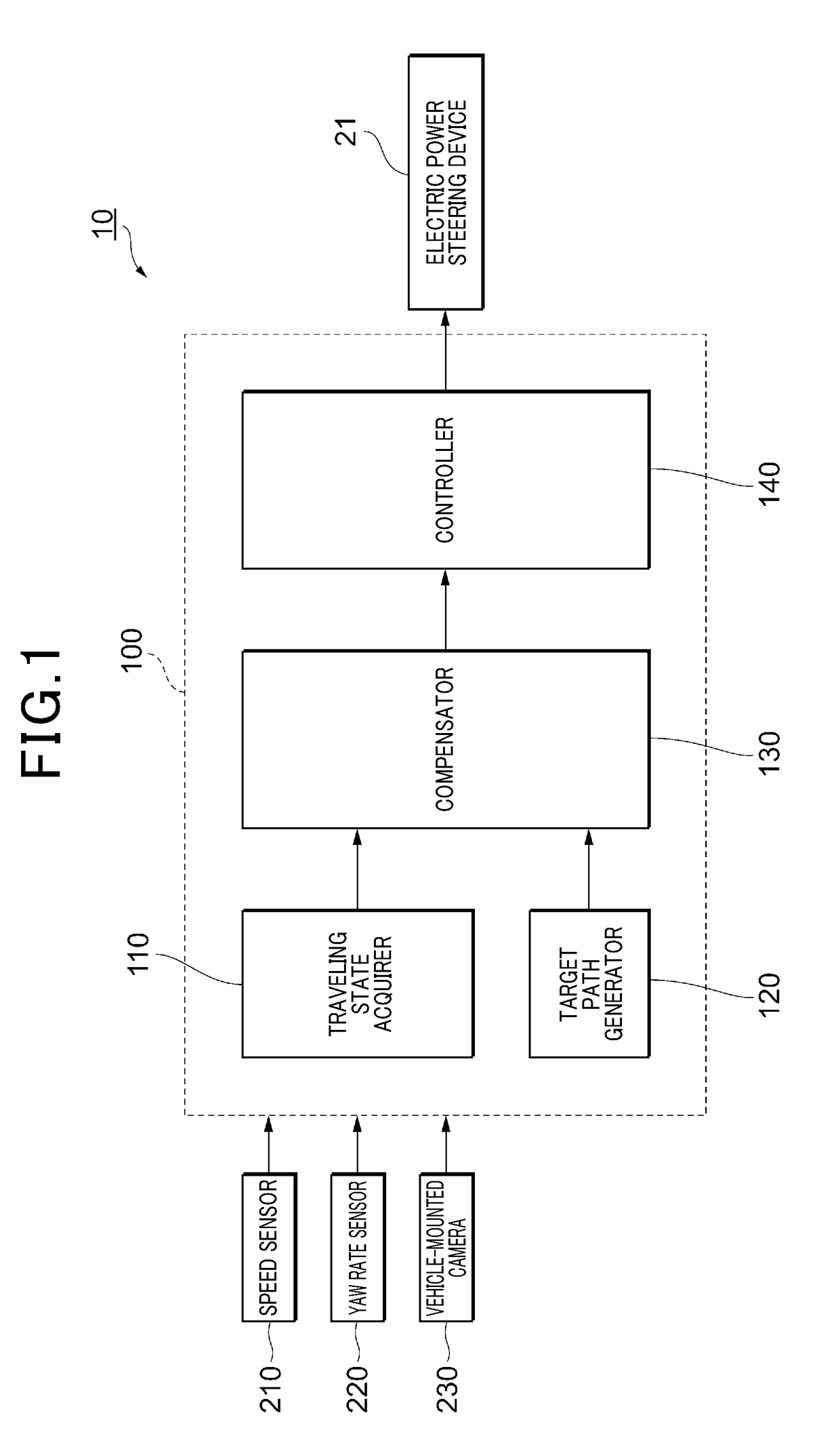
[0016]Referring to FIG. 1, the configuration of a driver assistance system 10 of the present embodiment will be described. The driver assistance system 10 is a system installed on a vehicle 20 (the vehicle 20 is not shown in FIG. 1, see FIG. 2), which is configured as a system for automatically performing the driving operation of the vehicle 20. The driver assistance system 10 can automatically steer the vehicle 20 by transmitting control signals to an electric power steering device 21 included in the vehicle 20. The driver assistance system 10 includes a speed sensor 210, a yaw rate sensor 220, a vehicle-mounted camera 230, and an arithmetic and logic unit 100.

[0017]The speed sensor 210 is a se...


PUM


Abstract

A driver assistance system that can reduce time delays in acquiring the traveling state of a vehicle and can stably control the vehicle. In the driver assistance system, a vehicle-mounted camera acquires an image including the boundary of a driving lane on which a vehicle travels. A target path generator generates a target path that is a path, on which the vehicle has to travel on the driving lane, based on the image. A traveling state acquirer acquires the traveling state of the vehicle on the driving lane based on the image. A controller performs steering control for causing the vehicle to travel along the target path based on the target path and the traveling state. A compensator compensates a time delay when the traveling state acquirer acquires the traveling state.

Description

CROSS-REFERENCE TO RELATED APPLICATION[0001]This application is based on and claims the benefit of priority from earlier Japanese Patent Application No. 2016-156150 filed Aug. 9, 2016, the description of which is incorporated herein by reference.BACKGROUNDTechnical Field[0002]The present disclosure relates to a driver assistance system that assists driving of a vehicle.Related Art[0003]In order to reduce traffic accidents and the burdens on drivers, driver assistance systems are being developed. The driver assistance system is a system that can automatically conduct a part or all of the driving operations performed by a vehicle driver or that can assist driving operations performed by a driver. Examples of such driving systems include systems that automatically perform all the manipulations, such as steering, in moving a vehicle, and systems that automatically perform only temporary driving operations, such as changing the lane. These examples also include systems that assist drivin...

Claims


Application Information

Patent Timeline
Patent Type & Authority Applications(United States)
IPC IPC(8): B62D15/02B62D6/00B62D6/02G05D1/02
CPCB62D15/025G05D1/0212G05D2201/0213B62D6/005B62D6/02G05D1/0246
Inventor OKAWA, ISAO
Owner DENSO CORP
Why Eureka
Try Eureka