Non-contact temperature sensing apparatus

a technology of temperature sensing apparatus and non-contact, which is applied in the direction of pyrometry using electric radation detectors, optical radiation measurement, instruments, etc., can solve the problems of increased manufacturing cost and time, and achieve the effect of improving thermal responsibility and reaction ra

Inactive Publication Date: 2018-02-22
LATTRON
View PDF0 Cites 0 Cited by
  • Summary
  • Abstract
  • Description
  • Claims
  • Application Information

AI Technical Summary

Benefits of technology

This patent is about a new way to measure temperature using a separate element that's attached to a circuit board. This new design improves how sensitive the temperature measurement is to changes in the environment.

Problems solved by technology

Accordingly, there are problems in that the manufacturing cost and time are increased.

Method used


Image

  • Non-contact temperature sensing apparatus
  • Non-contact temperature sensing apparatus
  • Non-contact temperature sensing apparatus

Examples


Embodiment Construction

[0015]Hereinafter, preferred embodiments of the invention will be described in more detail with reference to the accompanying drawings.

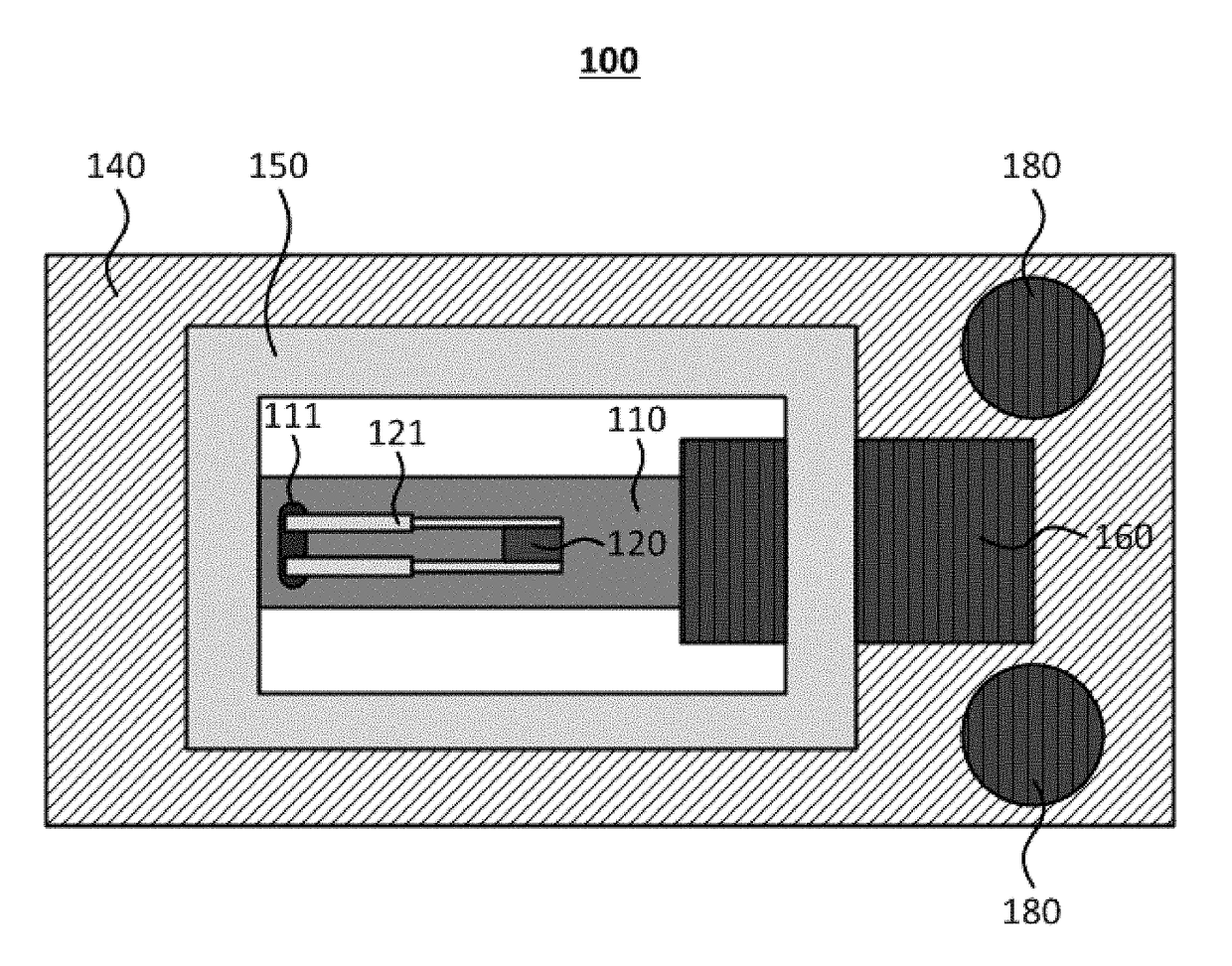
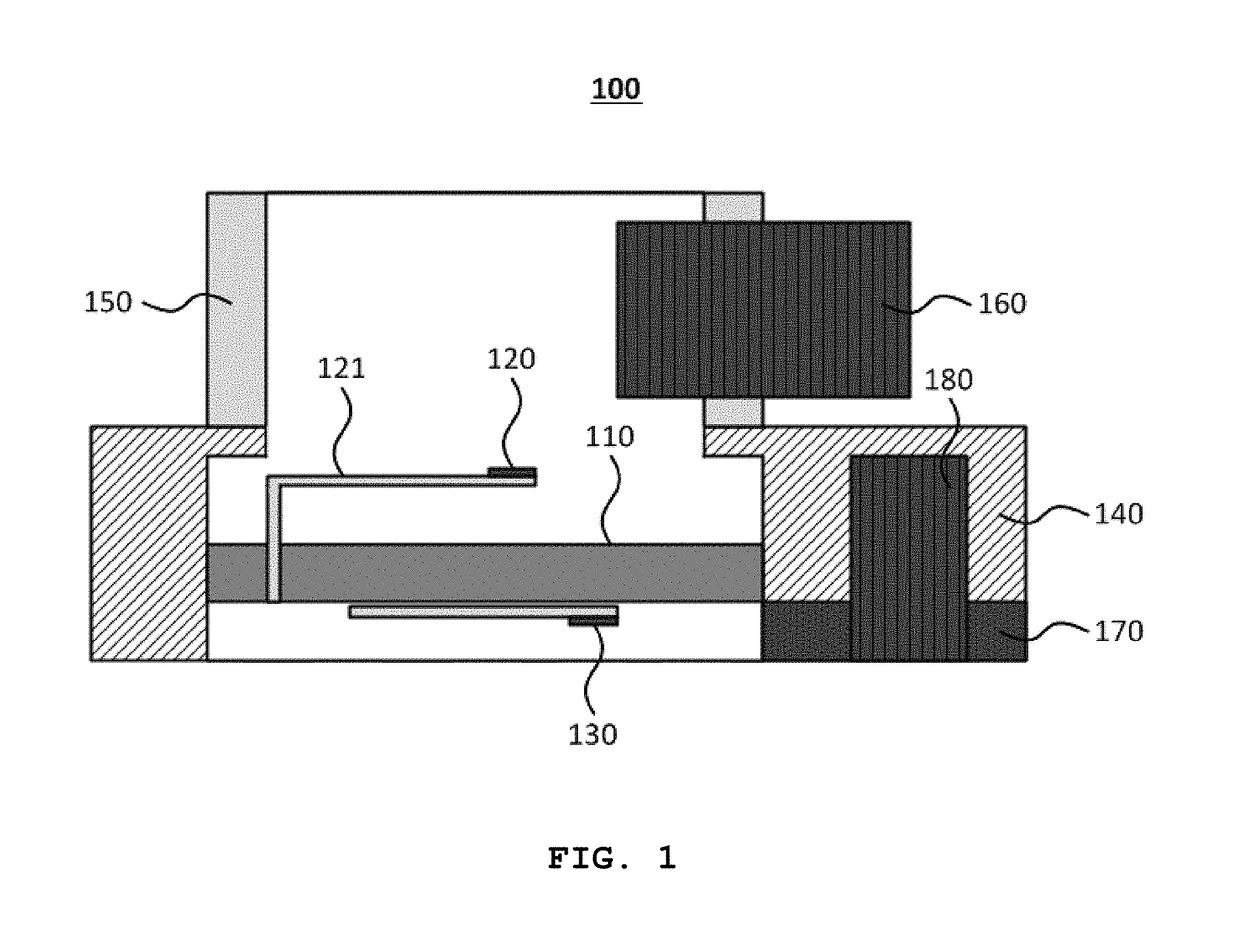
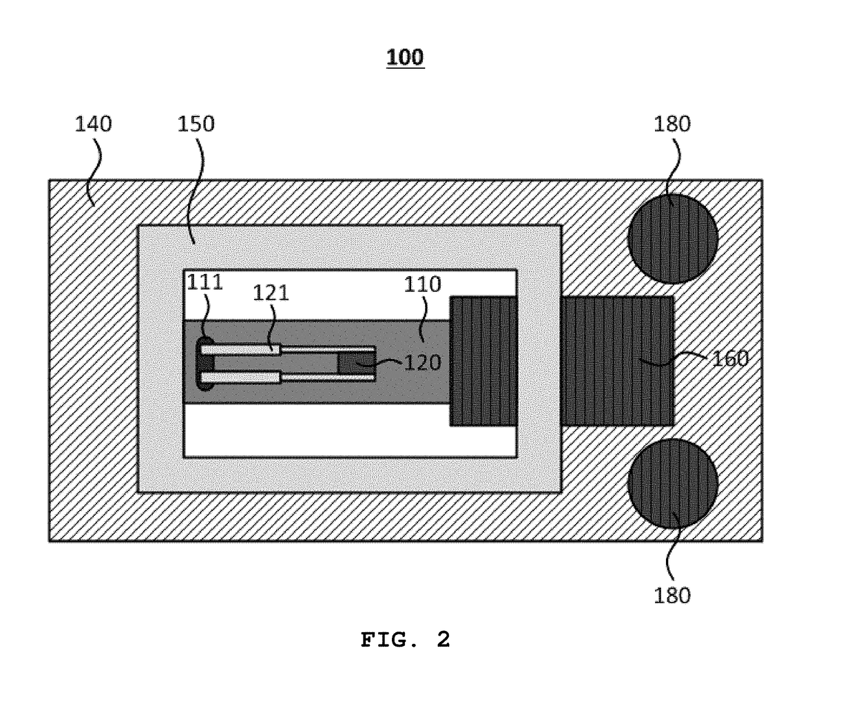
[0016]FIG. 1 is a sectional view illustrating a non-contact temperature sensing apparatus according to one embodiment of the present invention and FIG. 2 is a planar view illustrating the non-contact temperature sensing apparatus of FIG. 1. The non-contact temperature sensing apparatus (100) includes a substrate (110), a lead frame (121), an element (120) for sensing temperature, an element (130) for compensating temperature, and a case (140).

[0017]The substrate (110) includes a general PCB having wiring circuits and is connected to one end portion of the lead frame (121). The lead frame (121) is extended to an upper portion of the substrate (110). Preferably, a through hole 111 is formed at one side of the substrate (110). The lead frame (121) is vertically protruded from the through hole 111 and bended toward the upper portion of the substrate (110...


PUM


Abstract

Disclosed is a non-contact temperature sensing apparatus. The non-contact temperature sensing apparatus includes a substrate connected to one end portion of a lead frame; the lead frame extended to an upper portion of the substrate; an element for sensing temperature attached to the other end portion of the lead frame; and an element for compensating temperature attached to a lower surface of the substrate, wherein the element for sensing temperature is separated from the substrate, thereby increasing a thermal responsibility.

Description

BACKGROUND OF THE INVENTION1. Field of the Invention[0001]The present invention relates to a non-contact temperature sensing apparatus and, more specifically, relates to a non-contact temperature sensing apparatus in that an element for sensing temperature is attached to an upper portion of a PCB and the element for sensing temperature is separated from the PCB, thereby improving thermal responsibility and reaction rate thereof.2. Description of Related Art[0002]In the printing devices of applying an electro photographic system, such as a copy machine, a printer, and a facsimile machine etc., a toner is melted on a paper to be fixed by using a thermal fixing machine. At this time, a detecting element such as a thermistor serves to detect the surface temperature of a heat roller of a drum so as to stabilize the fixing condition of the thermal fixing machine.[0003]In the Japanese Publication Patent 2010-043930, the surface temperature of the heat roller of the drum is detected through...

Claims


Application Information

Patent Timeline
Patent Type & Authority Applications(United States)
IPC IPC(8): G01J5/22G01J5/00G01J5/04G01J5/06
CPCG01J5/22G01J5/0007G01J2005/068G01J5/06G01J5/042G01J5/0843G01J5/04G01J5/10G01J5/0806G01J5/0831G01J5/064G01J1/0411G01J5/061G01J5/20
Inventor LEE, WONKYOUNGLEE, CHUNGKOOK
Owner LATTRON
Why Eureka
Try Eureka