Surface cleaning apparatus

Active Publication Date: 2018-03-01
OMACHRON INTPROP
View PDF1 Cites 44 Cited by
  • Summary
  • Abstract
  • Description
  • Claims
  • Application Information

AI Technical Summary

Benefits of technology

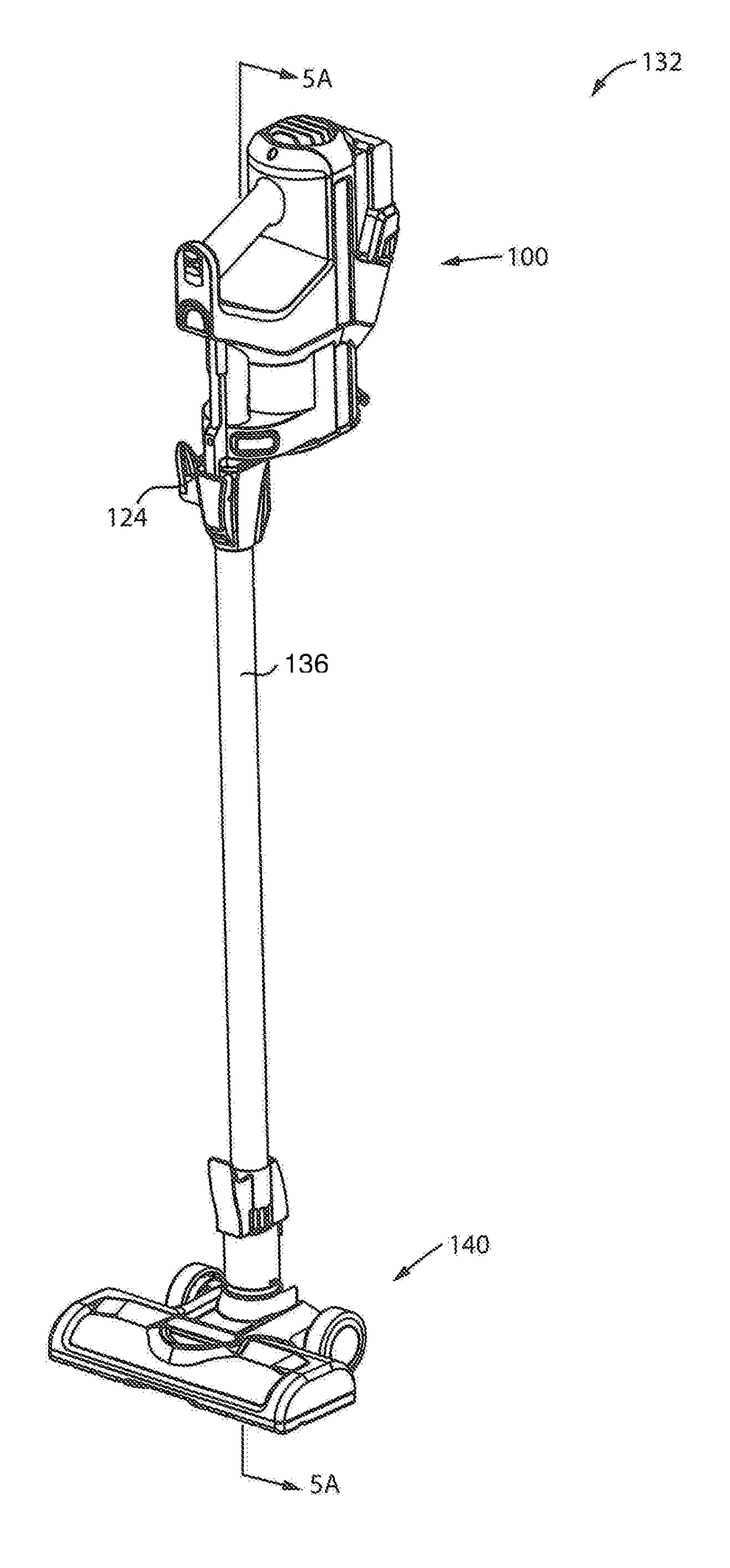
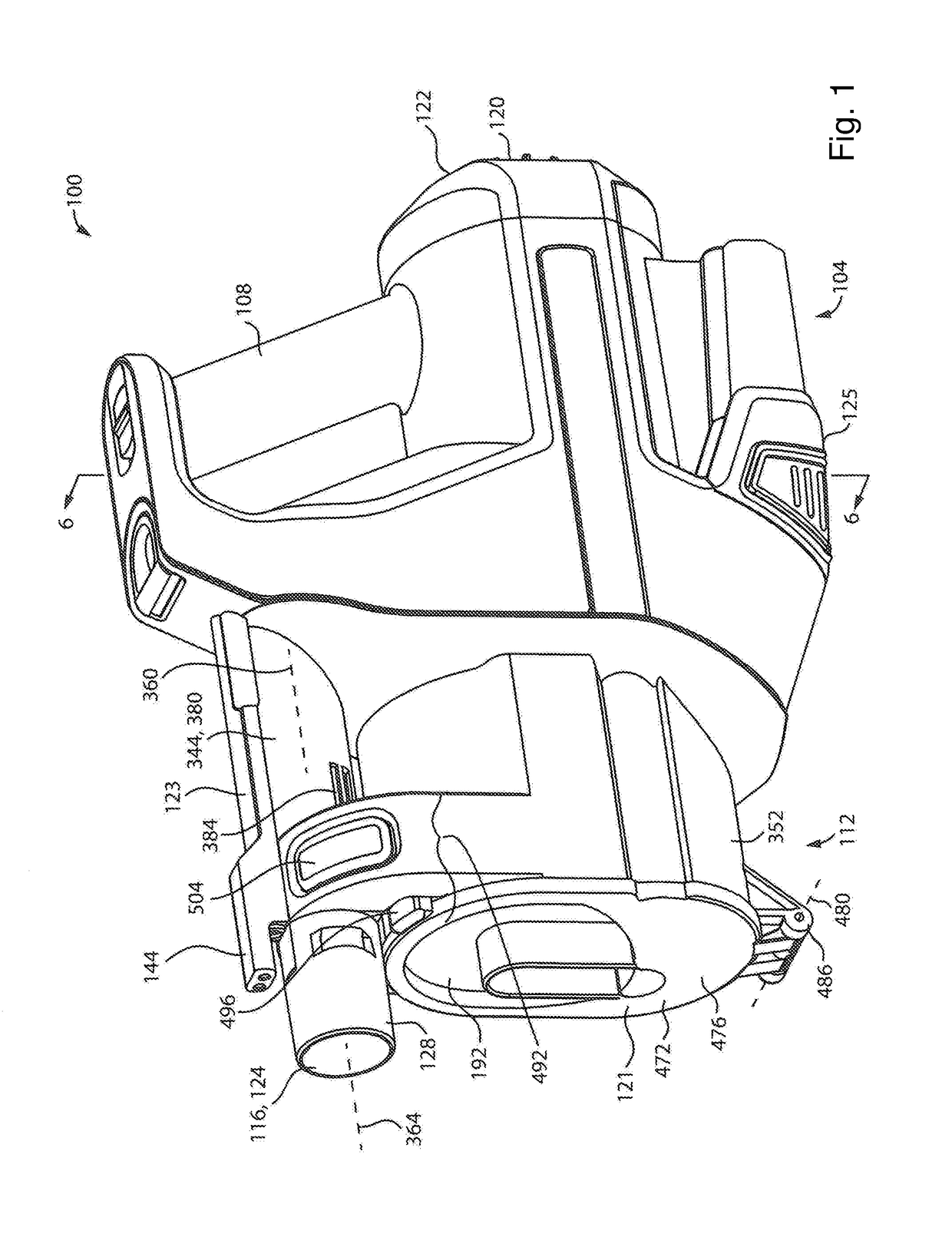
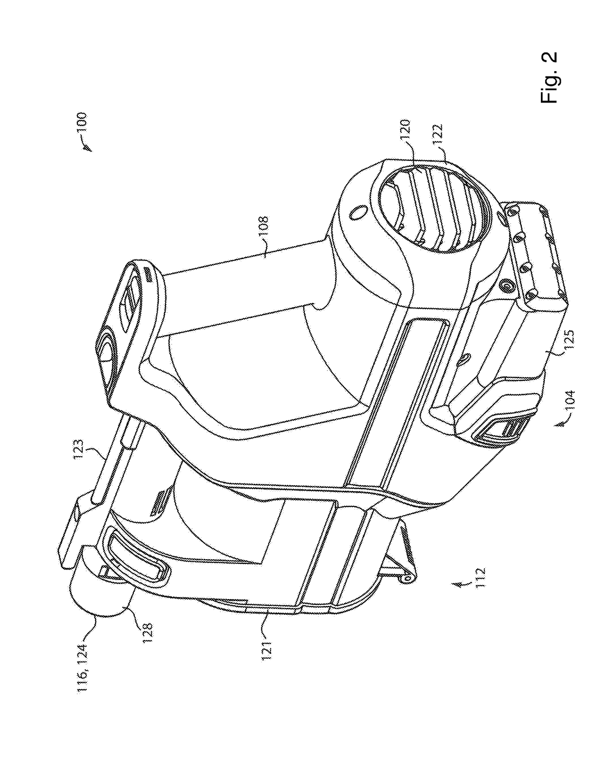
[0055]In accordance with another aspect of this disclosure, the air treatment member, e.g., a cyclone unit, may be removably mounted to the rest of the hand vacuum cleaner. The air treatment member may include a dirty air inlet that is connectable to an upper end of a longitudinally extending rigid member (e.g., which may be hollow to enable airflow therethrough) and a surface cleaning head may be provided (preferably removably connected) to a lower end of the longitudinally extending rigid member. When assembled as an upright or stick vacuum cleaner with the hand vacuum cleaner drivingly connected to the surface cleaning head by the longitudinally extending rigid member (e.g., a rigid wand), the handle of the hand vacuum cleaner may be used to steer the surface cleaning head. An advantage of this configuration is that the hand vacuum cleaner may be easily converted to an upright or stick vacuum cleaner.
[0056]In such a configuration, lateral stresses (i.e., stresses transverse to the longitudinal forward/rearward axis of the hand vacuum cleaner) may occur as the handle of the hand vacuum cleaner is used to steer the surface cleaning head. In order to assist in stabilizing the joint of the air treatment member an

Problems solved by technology

For example, it may be unlikely that a user would try and empty the dirt collection region when an accessory tool is connected.
In some e

Method used


Image

  • Surface cleaning apparatus
  • Surface cleaning apparatus
  • Surface cleaning apparatus

Examples


Example

[0255]Numerous embodiments are described in this application, and are presented for illustrative purposes only. The described embodiments are not intended to be limiting in any sense. The invention is widely applicable to numerous embodiments, as is readily apparent from the disclosure herein. Those skilled in the art will recognize that the present invention may be practiced with modification and alteration without departing from the teachings disclosed herein. Although particular features of the present invention may be described with reference to one or more particular embodiments or figures, it should be understood that such features are not limited to usage in the one or more particular embodiments or figures with reference to which they are described.

[0256]The terms “an embodiment,”“embodiment,”“embodiments,”“the embodiment,”“the embodiments,”“one or more embodiments,”“some embodiments,” and “one embodiment” mean “one or more (but not all) embodiments of the present invention(...


PUM


Abstract

A surface cleaning apparatus has a dirty air inlet and an air treatment member. The air treatment member includes a dirt collection region having an openable door. When an accessory is connected to the dirty air inlet, the openable door is inhibited from opening.

Description

CROSS-REFERENCE TO RELATED APPLICATIONS[0001]This application is a continuation in part of co-pending U.S. patent application Ser. No. 15 / 095,714, which was filed Apr. 11, 2016 and is incorporated herein in its entirety by reference.FIELD[0002]The specification relates to surface cleaning apparatus. In a preferred embodiment, the surface cleaning apparatus comprises a portable surface cleaning apparatus, such as a hand vacuum cleaner or a pod.INTRODUCTION[0003]The following is not an admission that anything discussed below is part of the prior art or part of the common general knowledge of a person skilled in the art.[0004]Various types of surface cleaning apparatus are known. Surface cleaning apparatus include vacuum cleaners. Currently, a vacuum cleaner typically uses at least one cyclonic cleaning stage. More recently, cyclonic hand vacuum cleaners have been developed. See for example, U.S. Pat. No. 7,931,716 and US 2010 / 0229328. Each of these discloses a hand vacuum cleaner whic...

Claims


Application Information

Patent Timeline
IPC IPC(8): A47L9/10A47L5/24A47L9/16A47L9/32A47L9/12
CPCA47L9/106A47L5/24A47L9/1683A47L9/1666A47L9/165A47L9/1608A47L9/1691A47L9/322A47L9/12A47L5/225A47L5/28A47L9/0072A47L9/0081A47L9/122A47L9/22A47L9/2868
Inventor CONRAD, WAYNE ERNEST
Owner OMACHRON INTPROP
Why Eureka
Try Eureka