Glare assembly for eye test display

Active Publication Date: 2015-11-05
THE HILSINGER
View PDF3 Cites 4 Cited by
  • Summary
  • Abstract
  • Description
  • Claims
  • Application Information

AI Technical Summary

Benefits of technology

The patent text describes a product that allows existing vision testing equipment to easily add the ability to test for glare without needing to replace the original equipment. The product can modify existing equipment without affecting the original installation.

Problems solved by technology

Unfortunately, in the light of day, and in real world conditions, such as driving at night with on-coming headlights directed at the driver, or in bright sunlight, the patient's vision may be quite different due to bright light passing through the lens of the eye.

Method used


Image

  • Glare assembly for eye test display
  • Glare assembly for eye test display
  • Glare assembly for eye test display

Examples


Embodiment Construction

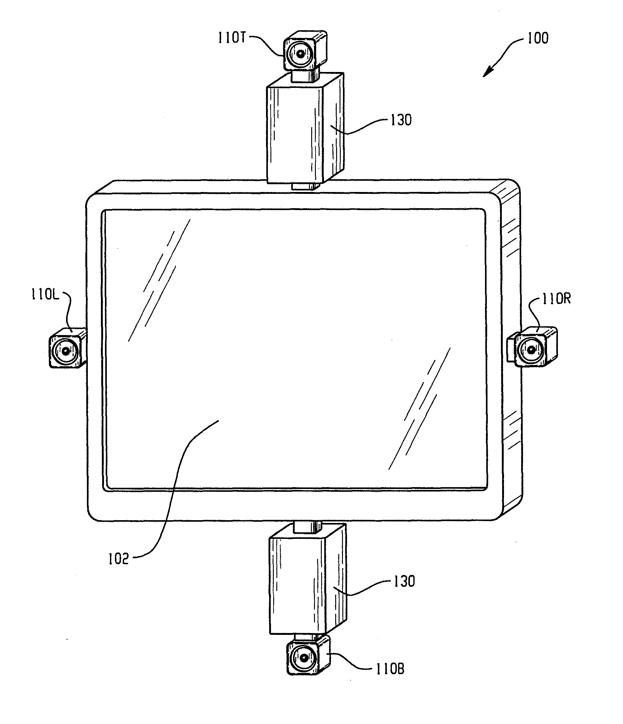
[0021]Turning first to FIG. 1, there is a shown a monitor 100 used to display a vision test operated by software from an associated computer (not shown), for example, of the type as shown and described in U.S. Published Application No. 20040036840A1. The illustrated monitor is rectangular, for example having a 16×9 rectangular aspect ratio. Although the illustrated monitor is of a liquid crystal display (LCD) type, it is also contemplated that other types of monitor such as a cathode ray tube (CRT), LED, etc. monitor could be employed without departing from the scope and intent of the present disclosure. Display face 102 is controlled by the vision testing software. The testing usually occurs in a dark room in order to provide greater control over the luminance associated with the monitor and thus a more standardized testing. A patient is spaced a predetermined distance from the monitor during the testing procedure, and the size of the characters on the screen are controlled and cal...


PUM


Abstract

A monitor / display is used to display a vision test. A patient is spaced a predetermined distance from the monitor / display during the testing procedure, and individual, multiple LED housings are equally spaced about a center point of the monitor / display to direct light toward the patient during at least a portion of the test procedure. The light emanating from the individual housings is a diffuse, unfocused light to simulate glare, and the intensity of the light may be selectively altered. Conducting vision testing under glare conditions determines if there is any reduction or fall off in the patient's vision under such circumstances and provides an indication of whether the patient may require cataract surgery or has another ocular problem. An assembly allows an existing vision testing system to be easily modified to provide glare light testing capabilities.

Description

[0001]This continuation-in-part application claims the priority benefit of U.S. application Ser. No. 14 / 047,467, filed Oct. 7, 2013, now U.S. Pat. No. 8,992,022, which is a continuation of and claims the priority benefit of Ser. No. 12 / 911,473, filed 25 Oct. 2010, now U.S. Pat. No. 8,550,631, which application claims the priority benefit of U.S. provisional application Ser. No. 61 / 254,410, filed 23 Oct. 2009, the disclosure of each case is expressly incorporated herein in its entirety.BACKGROUND OF THE DISCLOSURE[0002]This disclosure relates to an eye test assembly, and more particularly to an eye test assembly that displays an eye chart on a computer monitor and the eye test is run by software or a conventional vision test shown a projector display. Further, the present disclosure relates to a glare assembly for use with such a display or monitor that is useful in diagnosing cataracts or other ocular problems or issues associated with a patient. Under normal testing conditions, a p...

Claims


Application Information

Patent Timeline
IPC IPC(8): A61B3/032A61B3/00
CPCA61B3/0008A61B3/032A61B3/005A61B3/063
Inventor BUTLER, KEVIN A.
Owner THE HILSINGER
Why Eureka
Try Eureka