Water-spraying mop

a technology of water spraying mop and water pipe, which is applied in the field of cleaning products, can solve the problems of low stability of spraying water and easy squeezing and achieve the effects of improving the connection stability, reducing assembly process errors, and simple and reasonable structure design of the water spraying pipelin

Active Publication Date: 2018-03-01
JIAXING JACKSON TRAVEL PROD CO LTD
View PDF0 Cites 8 Cited by
  • Summary
  • Abstract
  • Description
  • Claims
  • Application Information

AI Technical Summary

Benefits of technology

[0034]First, the structural design of the pipeline of the water-spraying mop is simple and reasonable, effectively protecting the water-spraying pipeline and allowing the liquid to flow smoothly.
[0035]Second, the first circumferential single-direction positioning structure and the second circumferential single-direction positioning structure of the mop rod enable the present invention to be precisely and efficiently assembled, thereby reducing errors in the assembly process. Meanwhile, such a single-direction positioning structure greatly improves the connecting stability between the mop rod and the liquid-spraying base.
[0036]Third, the present invention allows the cleaning fluid to be sprayed while the mop head passes through the water-squeezing frame, thus enabling the mop cloth on the mop head to be conveniently cleaned. After being squeezed, the mop head can re-enter into the channel, and cleaning fluid can be re-sprayed to the mop cloth, greatly enhancing the cleaning effect of the water-spraying mop, and making the cleaning fluid easily and conveniently sprayed.

Problems solved by technology

However, the mop rod and the mop head of such a traditional water-spraying mop need to be rotated and bent during use, making the water-spraying pipeline easily squeezable.
Thus, the obstructed pipeline can lead to a low stability of spraying water.

Method used


Image

  • Water-spraying mop
  • Water-spraying mop
  • Water-spraying mop

Examples


embodiment 1

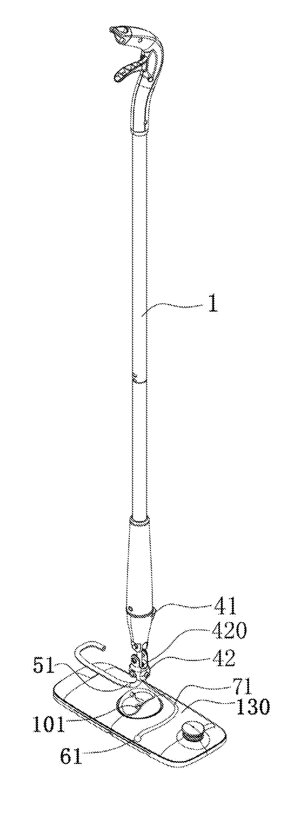
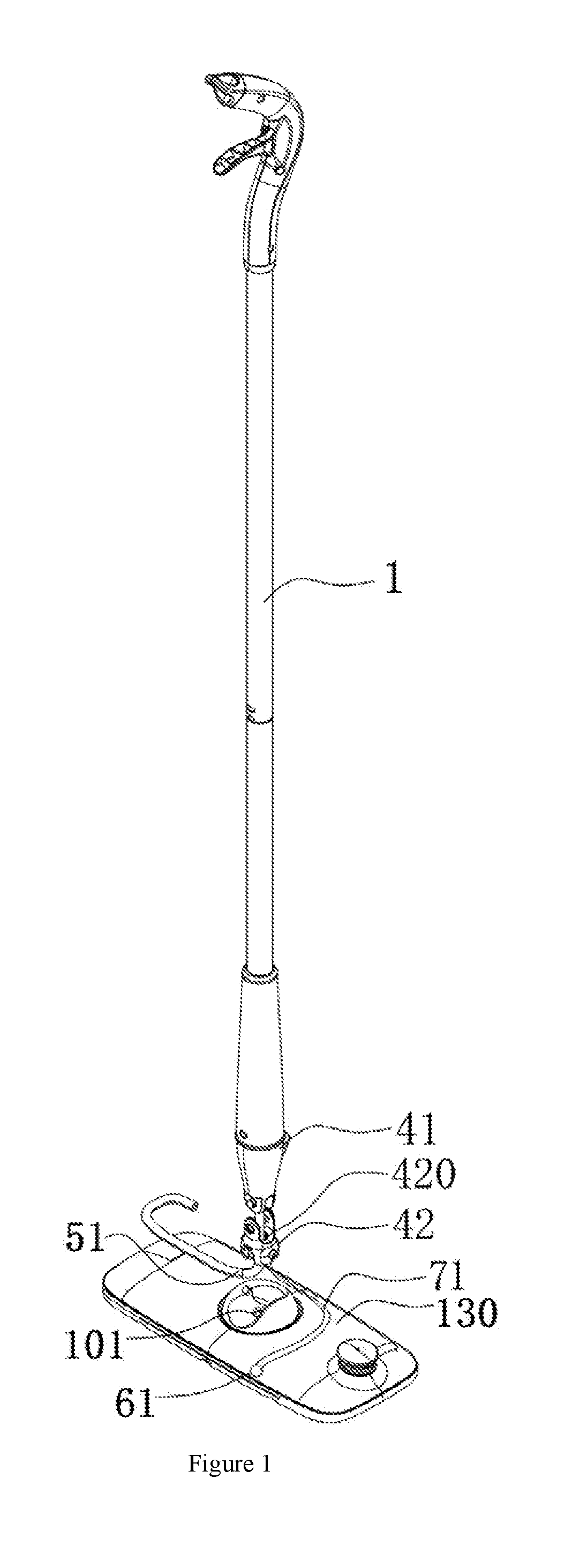
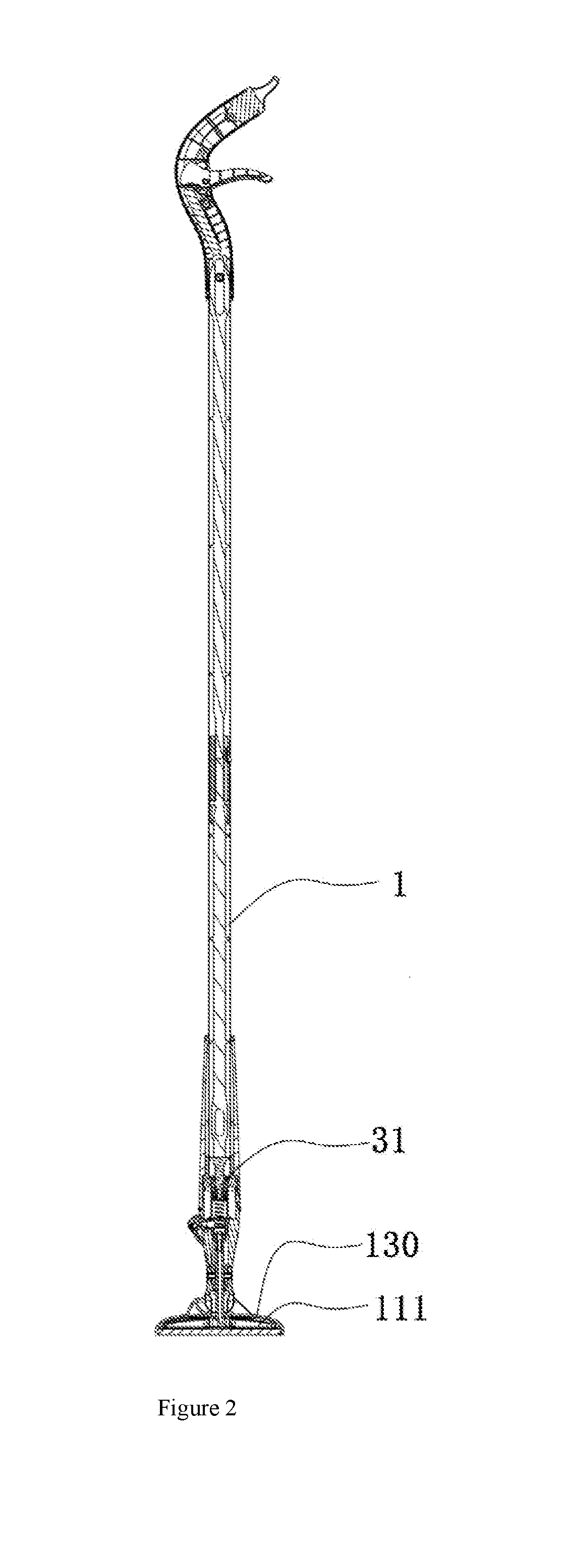
[0061]As shown in FIGS. 1-3, the water-spraying mop comprises a mop head 130, a mop rod 1, a water-spraying pump 31 and a universal connecting mechanism. A water tank 111 is disposed at the mop head 130. The mop head 130 is connected to the mop rod 1, and the water-spraying pump 31 is disposed on the mop rod 1. The mop rod 1 is connected to the mop head 130 through the universal connecting mechanism. The universal connecting mechanism comprises an upper connector 41 and a lower connector 42. One end of the upper connector 41 is fixed to the mop rod 1, and the other of the upper connector 41 is hinged with one end of the lower connector 42. Namely, the upper connector 41 is rotationally connected with the lower connector 42. The other end of the lower connector 42 is hinged with the other end of the mop head 130. One hinged end of the upper connector 41 is perpendicular to the other hinged end of the upper connector 41, thereby achieving a universal movement. The mop head 130 is prov...

embodiment 2

[0066]As shown in FIGS. 4-9, the water-spraying mop 1 is a structure composed of jointed rod bodies. The mop rod 1 comprises an upper rod body 21 and a lower rod body 22. A rod body connecting structure 26, which enables the upper rod body 21 and the lower rod body 22 to be jointed or separated, is disposed between the upper rod body 21 and the lower rod body 22. An upper inner rod 23 is inserted into the upper rod body 21, and a lower inner rod 24 is disposed in the lower rod body 22. A control mechanism 27, which can propel the upper inner rod 23 to move in an axial direction, is disposed between the upper rod body 21 and the upper inner rod 23. An elastic reset mechanism 30, which enables the lower inner rod 24 moving downwardly in an axial direction to recover to the original position, is connected to the lower rod body 22 or the lower inner rod 24. After the upper rod body 21 and the lower rod body 22 are jointed through the rod-body connecting structure 26, the upper inner rod...

embodiment 3

[0073]As shown in FIGS. 10-18, the mop rod 1 is provided with a liquid-spraying base 3 used for mounting the water pump. A first circumferential single-direction positioning structure 8, which enables the liquid-spraying base 3 to be circumferentially positioned in a single direction relative to the mop rod 1 so that the orientation of the sprayer 4 can be fixed, is disposed between the liquid-spraying base 3 and the mop rod 1. A liquid-spraying mechanism 5 having a sprayer 4 is disposed on the liquid-spraying base 3, and the other end is connected to a handle body 6. One side of the handle body 6 is provided with a trigger 7. The first circumferential single-direction positioning structure 8, which enables the liquid-spraying base 3 to be circumferentially positioned in a single direction relative to the mop rod 1 so that the orientation of the sprayer 4 can be fixed, is disposed between the liquid-spraying base 3 and the mop rod 1. Meanwhile, a second circumferential single-direct...


PUM


Abstract

A water-spraying mop comprising a mop rod, a mop head and a universal joint that rotationally connects the mop head and the mop rod; the mop rod comprises a water-squeezing frame that is disposed on the mop rod, and is capable of moving relative to the mop rod in an axial direction; the water-squeezing frame comprises a channel for allowing the mop head to pass through, a water-squeezing portion that is disposed in the channel, and faces the mop cloth while the mop head passes through the channel, and a liquid-spraying system consisted of a water tank, a water pump and a dynamic mechanism used for propelling the water pump to spray liquid; the water tank is disposed at the mop head, and the water pump is disposed in the mop rod.

Description

TECHNICAL FIELD OF THE INVENTION[0001]The present invention relates to the technical field of cleaning products, and more particularly, to a water-spraying mop having a self-cleaning performance.BACKGROUND OF THE INVENTION[0002]Chinese patent CN204541992U discloses a water-spraying mop comprising a mop rod. The lower end of the mop rod is connected to a mop head, and the lower portion of the mop head is provided with a mop cloth. Furthermore, the lower portion of the mop rod is provided with a water-spraying apparatus. The water-spraying apparatus comprises a water-spraying mouth and a water-storing pot. The upper end of the mop rod is provided with an armrest, and a switch used for controlling the water-spraying apparatus is disposed on the armrest. The water-spraying mouth is a high pressure fine atomizing nozzle, and the water-spraying direction is angled towards the front of the mop head. However, the mop rod and the mop head of such a traditional water-spraying mop need to be r...

Claims


Application Information

Patent Timeline
Patent Type & Authority Applications(United States)
IPC IPC(8): A47L13/22A47L13/14A47L13/256
CPCA47L13/22A47L13/14A47L13/256
Inventor LI, JING
Owner JIAXING JACKSON TRAVEL PROD CO LTD
Why Eureka
Try Eureka