Planar illumination apparatus and substrate

Active Publication Date: 2018-03-01
MINEBEAMITSUMI INC
View PDF12 Cites 2 Cited by
  • Summary
  • Abstract
  • Description
  • Claims
  • Application Information

AI Technical Summary

Problems solved by technology

However, to consider a case in which the series wiring is formed on the mounting surface of the FPC, when a distance between the LEDs adjacent to each other becomes small, it becomes difficult to arrange a cover lay (insulating layer) so as to cover the series wiring.
When solder used for soldering flows onto the series wiring narrow in wiring width fro

Method used


Image

  • Planar illumination apparatus and substrate
  • Planar illumination apparatus and substrate
  • Planar illumination apparatus and substrate

Examples


embodiment

Modification of Embodiment

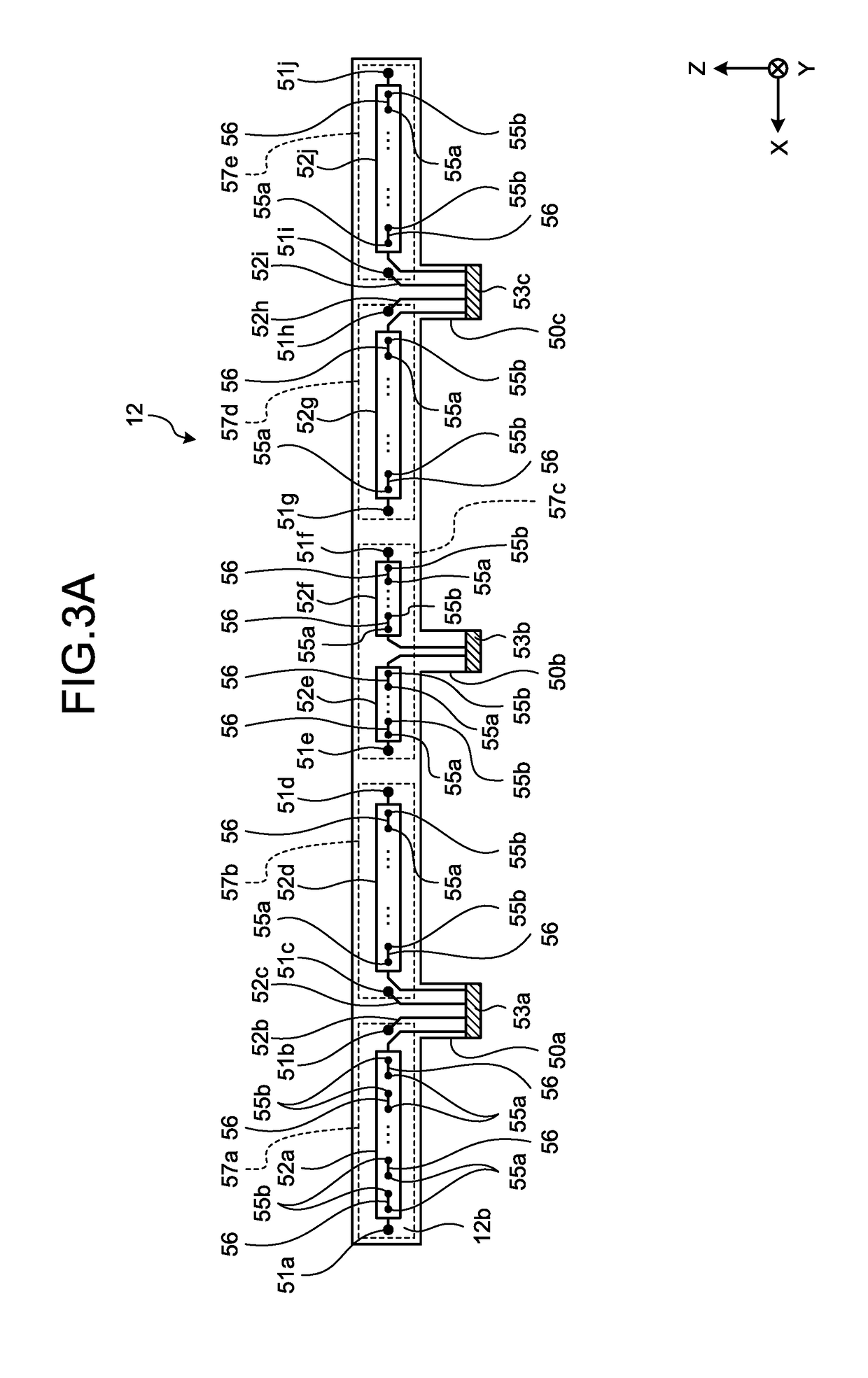
[0070]In the above-mentioned embodiment, a case is explained in which the number of the external connection parts 50 is three. However, the number of the external connection parts 50 is not limited to the case above. For example, the number of the external connection parts 50 may be reduced to two. Here, an embodiment such that the number of the external connection parts 50 is two is explained as a planar illumination apparatus according to a modification of the above-mentioned embodiment. In the explanation of a first modification, constitutional features identical with those in the above-mentioned embodiment are given the same numerals, and their repeated explanations may be omitted.

[0071]The planar illumination apparatus according to the modification differs from the planar illumination apparatus 10 according to the above-mentioned embodiment in that the planar illumination apparatus according to the modification is provided with only two external connec...


PUM


Abstract

A planar illumination apparatus according to an embodiment includes a light guide plate that outputs light entered into the light guide plate through a side face of the light guide plate, a plurality of light sources that are arranged on the side face side, and emit light to be entered into the side face, a substrate having a mounting surface where the light sources are mounted, and first wiring that is formed on an opposite surface opposite to the mounting surface of the substrate, and connects serially the light sources with each other.

Description

CROSS-REFERENCE TO RELATED APPLICATION(S)[0001]The present application claims priority to and incorporates by reference the entire contents of Japanese Patent Application No. 2016-166289 filed in Japan on Aug. 26, 2016 and Japanese Patent Application No. 2017-088637 filed in Japan on Apr. 27, 2017.BACKGROUND OF THE INVENTION1. Field of the Invention[0002]The present invention relates to a planar illumination apparatus and a substrate.2. Description of the Related Art[0003]There exists a planar illumination apparatus such that a plurality of light emitting diodes (LED) are arranged to face the light entering surface of a light guide plate in an opposed manner. In the planar illumination apparatus, for example, the LEDs are arranged in line on a mounting surface in the longitudinal direction of flexible printed circuits (FPC), and wiring each of which connects serially the LEDs adjacent to each other (hereinafter, referred to as “series wiring”) is formed on the mounting surface (see ...

Claims


Application Information

Patent Timeline
IPC IPC(8): F21V8/00
CPCG02B6/0068G02B6/009G02B6/0088G02B6/0083G02B6/0051G02B6/0053G02B6/0055F21V13/12F21V19/0025F21V23/005F21V23/06F21K9/61F21Y2115/10G02F1/133615G02B6/0091
Inventor FURUTA, MAKOTO
Owner MINEBEAMITSUMI INC
Why Eureka
Try Eureka