
Inkjet head and manufacturing method thereof

a manufacturing method and technology of inkjet head, applied in printing and other directions, can solve the problems of increasing the resistance of the wire, the width of the wire cannot be significantly reduced, and the width of the wire must be narrow, so as to increase the width and thickness of the wire, reduce the resistance of the electrode, and increase the density of the inkjet head.

Inactive Publication Date: 2009-05-19
FUJIFILM CORP
View PDF22 Cites 2 Cited by
  • Summary
  • Abstract
  • Description
  • Claims
  • Application Information

AI Technical Summary

Benefits of technology

[0021]The present invention has been contrived in view of such circumstances, and an object thereof is to provide an inkjet head and a manufacturing method thereof in which the discrete lead electrodes can be made thick, the width of the wiring portion can be reduced, and higher density can be achieved.

Problems solved by technology

But, when the matrix array has six or eight rows, there is drawback in which the width of the wiring must be made as narrow as possible due to the nozzle pitch so that the wiring resistance increases.
Also, in conventional methods such as sputtering and vapor deposition, since a thickness of several μm or more is difficult from the aspect of the film formation rate, the width of the wiring cannot be significantly reduced.
Therefore, there are drawbacks in which removal and surface polishing must be carried out in later steps in order to make the electrodes independent.
Therefore, there is a drawback in which it is difficult to form a wiring pattern with a constant hardness.
However, soldering in a two-dimensional array is also technically difficult from aspects of surface accuracy, warping, or pressure conditions.
In addition, there are also drawbacks such as degradation of element characteristics and the flow of solder into active areas due to soldering in the vicinity of active areas.
Therefore, those cannot directly be used for forming wiring in inkjet heads.

Method used


Image

  • Inkjet head and manufacturing method thereof
  • Inkjet head and manufacturing method thereof
  • Inkjet head and manufacturing method thereof

Examples


Embodiment Construction

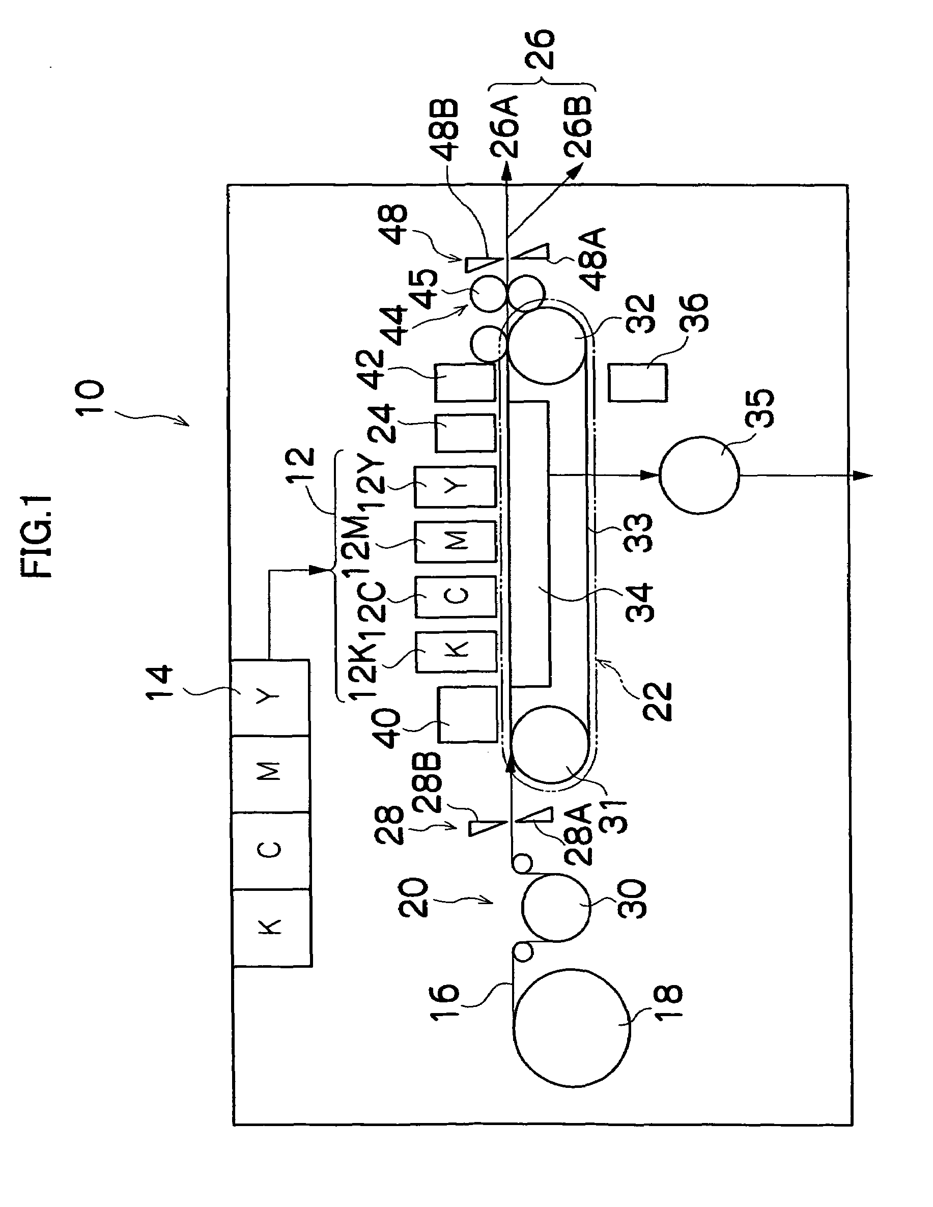
[0065]FIG. 1 is a general schematic drawing of an inkjet recording apparatus according to an embodiment comprising an inkjet head of the present invention.

[0066]As shown in FIG. 1, the inkjet recording apparatus 10 comprises: a printing unit 12 having a plurality of droplet discharge heads or print heads 12K, 12C, 12M, and 12Y for ink colors of black (K), cyan (C), magenta (M), and yellow (Y), respectively; an ink storing / loading unit 14 for storing inks to be supplied to the print heads 12K, 12C, 12M, and 12Y; a paper supply unit 18 for supplying recording paper 16; a decurling unit 20 for removing curl in the recording paper 16; a suction belt conveyance unit 22 disposed facing the nozzle face (ink-droplet discharge face) of the printing unit 12, for conveying the recording paper 16 while keeping the recording paper 16 flat; a print determination unit 24 for reading the printed result produced by the printing unit 12; and a paper output unit 26 for outputting image-printed recordi...


PUM


Abstract

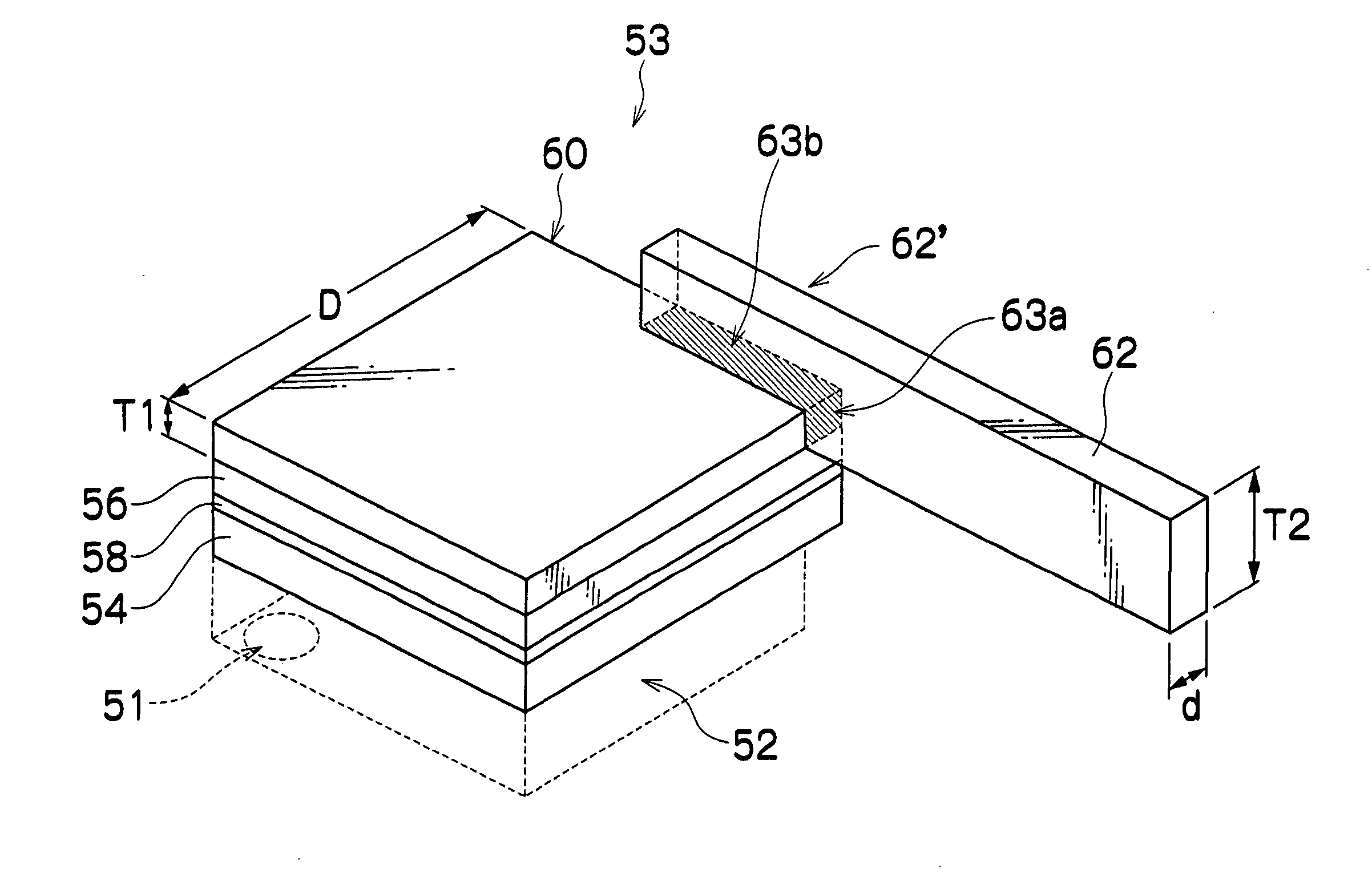
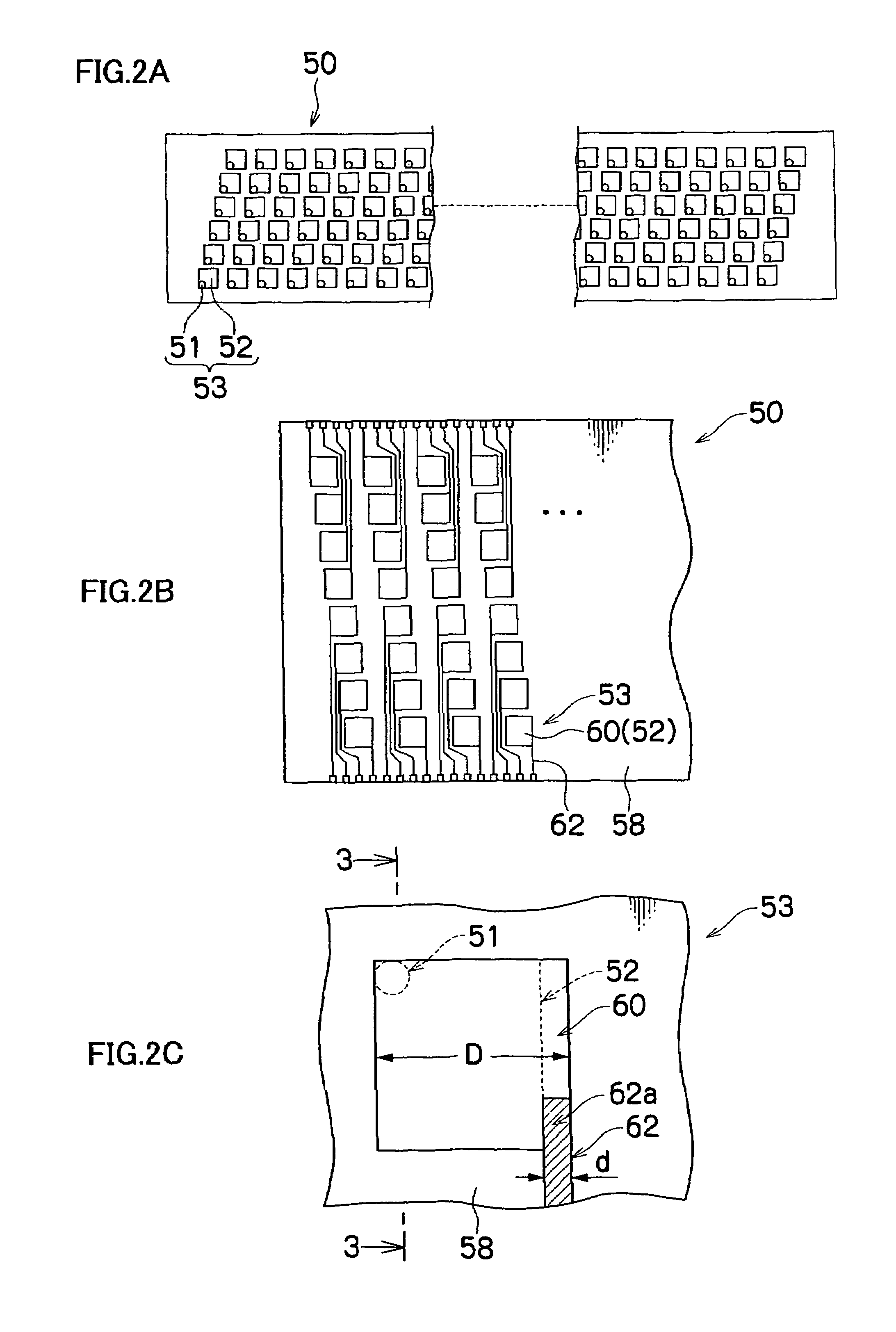
The inkjet head includes: a plurality of ink discharge nozzles which are arranged two-dimensionally; a plurality of pressure chambers which are in communication with the ink discharge nozzles so as to store ink, the pressure chambers being two-dimensionally arranged in correspondence with the ink discharge nozzles; a plurality of piezoelectric elements; a common electrode which is disposed on pressure chamber sides of the piezoelectric elements; a plurality of discrete electrodes which are disposed on sides of the piezoelectric elements opposite to the common electrode; and a plurality of discrete lead electrodes which feed electricity to the discrete electrodes, wherein: each of the piezoelectric elements is deformed by applying voltage to the common electrode and the discrete electrode so that a volume of the pressure chamber is varied to discharge a droplet of the ink from the ink discharge nozzle; and with respect to each pair of the discrete electrode and discrete lead electrode corresponding to each of the pressure chambers, when T1 is a thickness of the discrete electrode and T2 is a thickness of the discrete lead electrode which feed electricity to the discrete electrode, the discrete electrode and the discrete lead electrode are configured so that T1 and T2 satisfy the following formula: T1<T2.

Description

BACKGROUND OF THE INVENTION[0001]1. Field of the Invention[0002]The present invention relates to an inkjet head and a manufacturing method thereof, and more specifically to an inkjet head for discharging ink by using a piezoelectric element, and a manufacturing method of the inkjet head wherein wiring for discrete electrodes is formed by the aerosol method.[0003]2. Description of the Related Art[0004]Conventionally, an inkjet recording apparatus (an inkjet printer) that has an inkjet head (ink discharge head) with a plurality of arranged nozzles (ink discharge ports) and form images on a recording medium by discharging ink (ink droplets) from nozzles toward the recording medium as the inkjet head moves relative to the recording medium, are known as an image forming apparatus.[0005]For example, a known ink discharging method in such an inkjet recording apparatus is a piezoelectric method in which a diaphragm constituting a portion of a pressure chamber (ink chamber) is deformed by th...

Claims


Application Information

Patent Timeline
Patent Type & Authority Patents(United States)
IPC IPC(8): B41J2/05B41J2/14B41J2/16
CPCB41J2/14233B41J2/161B41J2/1632B41J2/1634B41J2/1642B41J2/1646B41J2002/14266B41J2002/14459B41J2002/14491
Inventor MITA, TSUYOSHI
Owner FUJIFILM CORP
Learn More