Deicing module for an aircraft and method for deicing

a technology for aircraft and wings, applied in the direction of de-icing equipment, wings, transportation and packaging, etc., can solve the problems of affecting the aerodynamic efficiency of wings and the limited approach of slower moving aircra

Active Publication Date: 2018-03-08
GE AVIATION SYST LLC
View PDF3 Cites 12 Cited by
  • Summary
  • Abstract
  • Description
  • Claims
  • Application Information

AI Technical Summary

Problems solved by technology

Contemporary turbo-prop engine aircraft include wings having surfaces that can be susceptible to ice accumulation in certain flying conditions.
Ice build-up

Method used


Image

  • Deicing module for an aircraft and method for deicing
  • Deicing module for an aircraft and method for deicing
  • Deicing module for an aircraft and method for deicing

Examples


Embodiment Construction

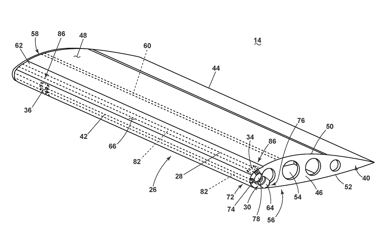
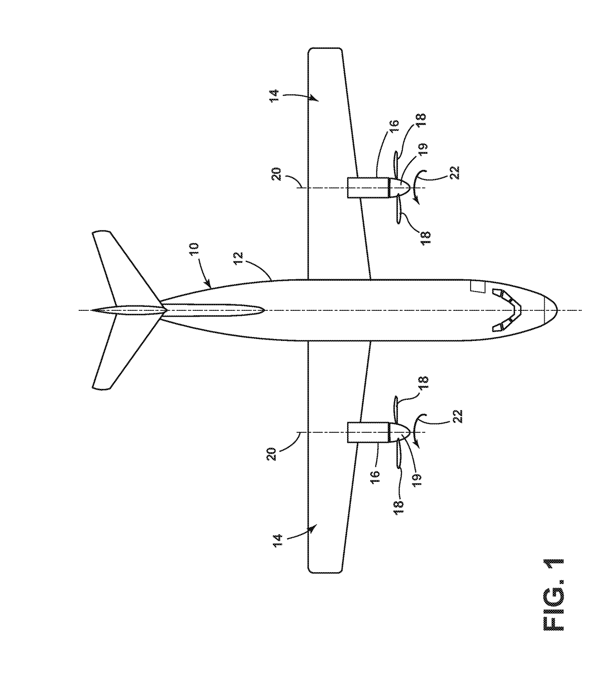
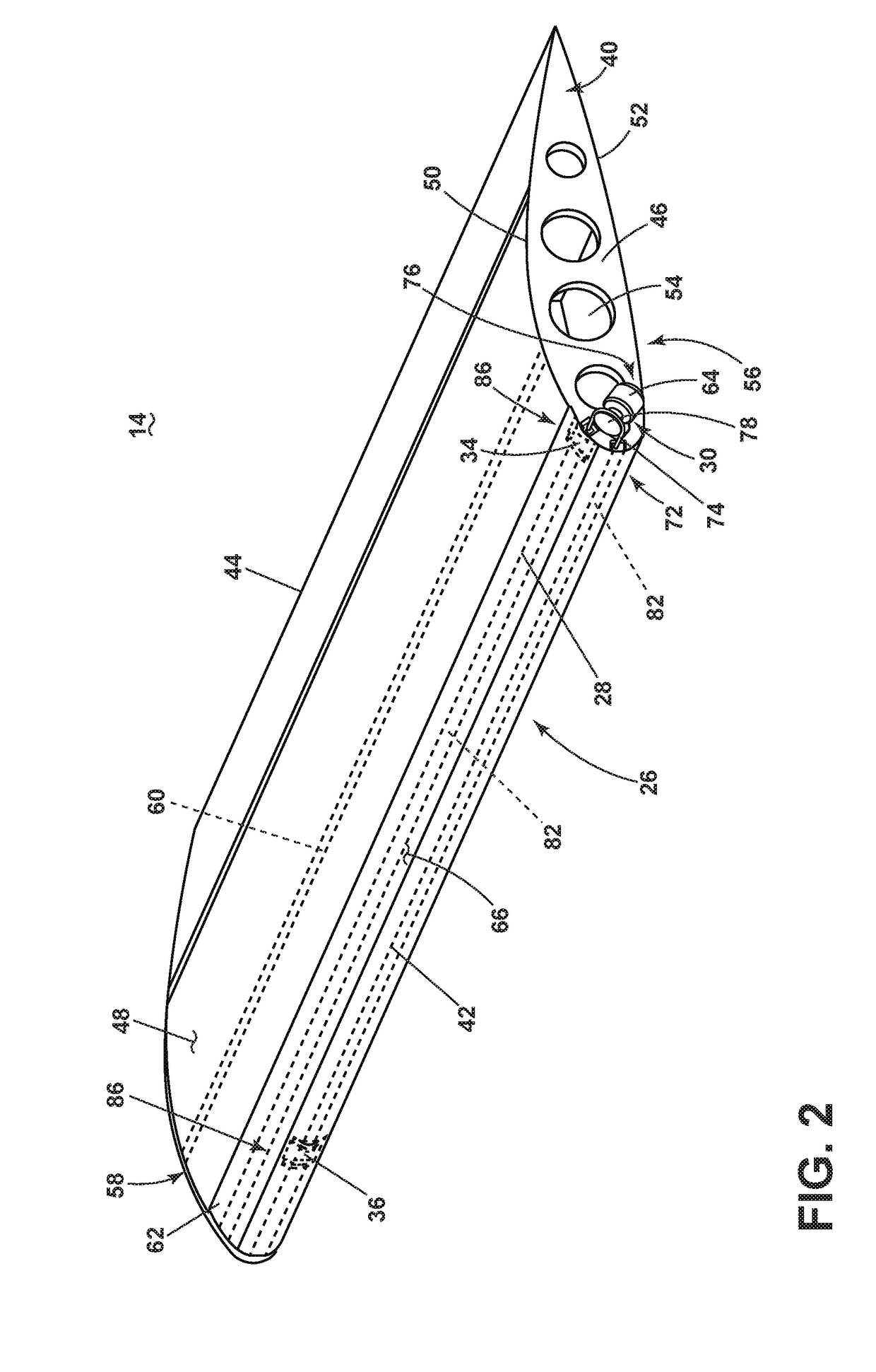
[0014]The various aspects described herein are related to preventing or reducing build-up, accumulation, or shedding of ice on an aircraft wing. Embodiments of the disclosure can be implemented in any environment, apparatus, or method for preventing or reducing ice on a surface, regardless of the function performed by the surface. By way of non-limiting example such surface is that of a wing of an aircraft where the aircraft can have a turbo-prop engine or turbo-fan jet engine or any other suitable engine for an aircraft. Thus, the remainder of this applications focuses on such an environment.

[0015]As used herein, the term “forward” or “upstream” refers to moving in a direction toward the engine inlet, or a component being relatively closer to the engine inlet as compared to another component. The term “aft” or “downstream” used in conjunction with “forward” or “upstream” refers to a direction toward the rear or outlet of the engine or being relatively closer to the engine outlet as...


PUM


Abstract

An apparatus and method for deicing a surface upon which ice accumulates, on for example an aircraft wing. The apparatus and method for the deicing module include an actuating component, a casing, and a movable member. The movable member breaks ice that has accumulated on a surface of the wing.

Description

BACKGROUND OF THE INVENTION[0001]Contemporary turbo-prop engine aircraft include wings having surfaces that can be susceptible to ice accumulation in certain flying conditions. Aircraft approved for flight into known icing conditions must include provisions to prevent unacceptable levels of ice accumulation on the wings. Ice build-up on the wings affects the aerodynamic efficiency of the wing. Limiting the amount of ice build-up or accumulation increases aerodynamic efficiency.[0002]Conventional aircraft can include electrical or pneumatic heating systems to provide cyclic or continuous heating of aerodynamic surfaces and / or propeller blades to control the build-up, accumulation, or shedding of ice. Conventional aircraft can also use an inflated rubber membrane (often called a “boot”) which is cyclically inflated with air pressure. This approach is limited to slower moving aircraft due to the increased aerodynamic drag penalty. Another approach is a set of electromagnetic or piezo-e...

Claims


Application Information

Patent Timeline
IPC IPC(8): B64D15/16B64C3/26
CPCB64C3/26B64D15/16
Inventor SCHWICHTENBERG, BRYAN E.MILLER, LANCE F.OPIFICIUS, JULIAN A.
Owner GE AVIATION SYST LLC
Why Eureka
Try Eureka