Ice protection system

a technology of ice protection system and rotary aircraft, which is applied in the direction of vehicles, de-icing equipment, vertical landing/take-off aircraft, etc., can solve the problems of reducing the lift efficiency of the proprotor, affecting performance, and catastrophic failure,

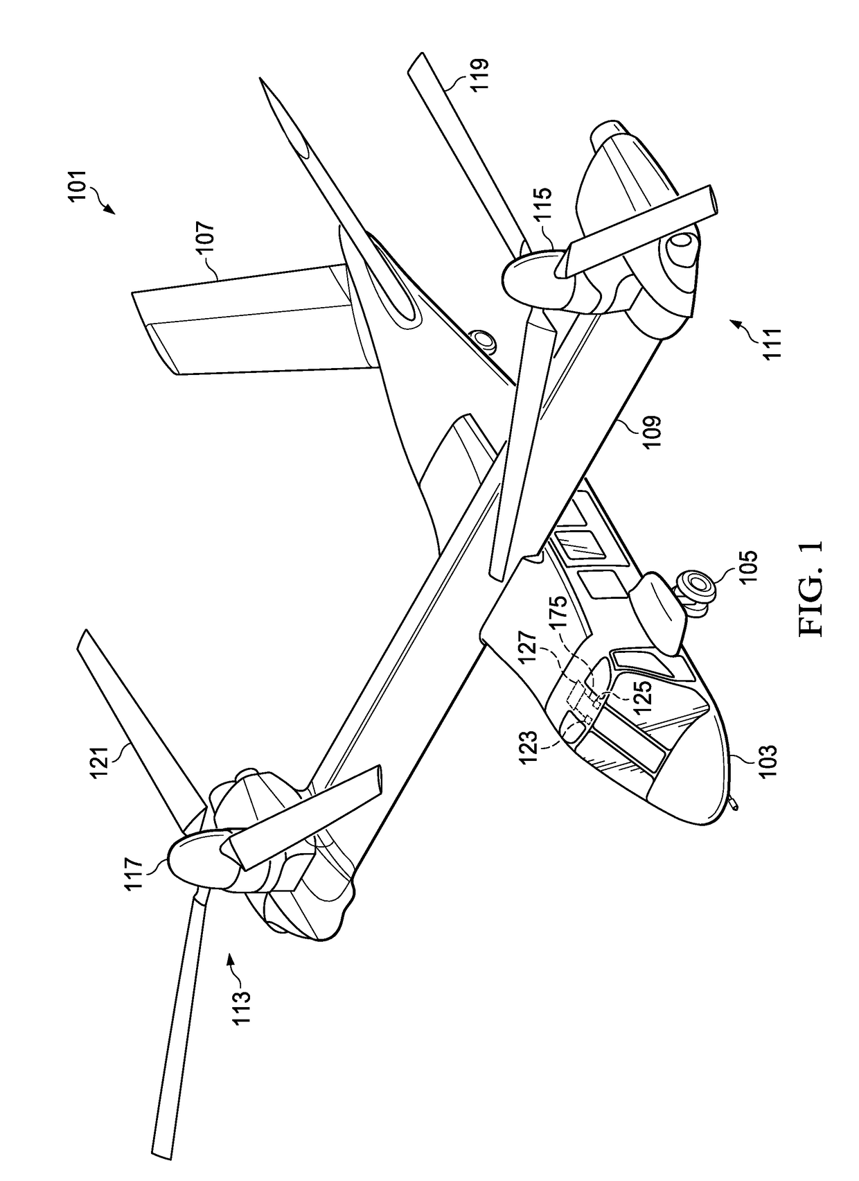
Active Publication Date: 2019-03-21
BELL HELICOPTER TEXTRON INC
View PDF15 Cites 10 Cited by
  • Summary
  • Abstract
  • Description
  • Claims
  • Application Information

AI Technical Summary

Problems solved by technology

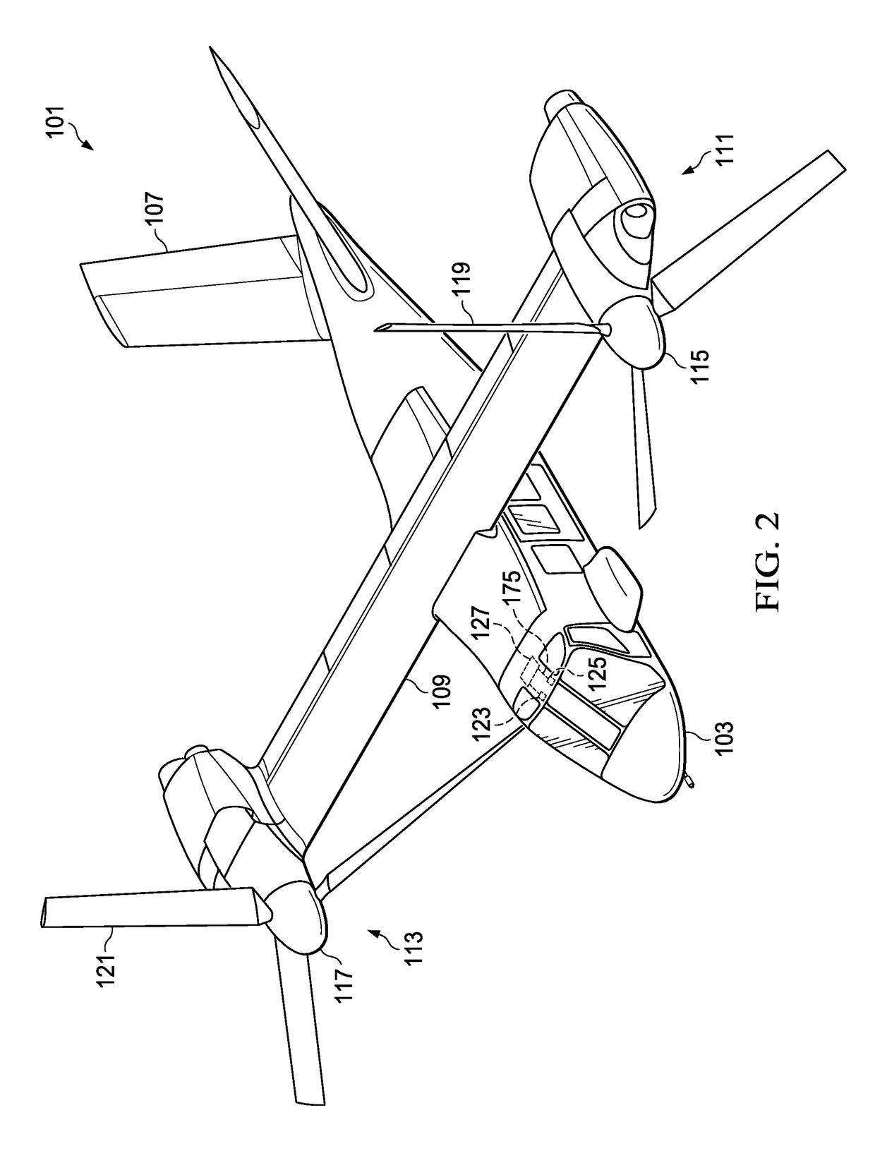
Vertical takeoff and landing aircraft (“VTOL”) can have ice-buildup that can negatively impact performance and cause catastrophic failure.
Ice accumulation greatly reduces proprotor lift efficiency, and, because of the proprotor diameter and aircraft weight ratio, tiltrotors are significantly affected in their ability to land or hover by ice accumulation on the blades of the proprotor.
The spanwise zone configuration suitable for helicopter rotor blades has not been implemented in tiltrotor aircraft rotor blades due to the concern with shedding large chunks of ice in airplane and transition modes.
If large chunks of ice are shed during airplane and transition modes, large chunks of ice could hit and damage the tiltrotor fuselage.
Electrical connections are notoriously weak points in a tiltrotor rotor blade, which is subjected to higher dynamic motion and bending and higher strain levels as compared to a conventional helicopter blade.
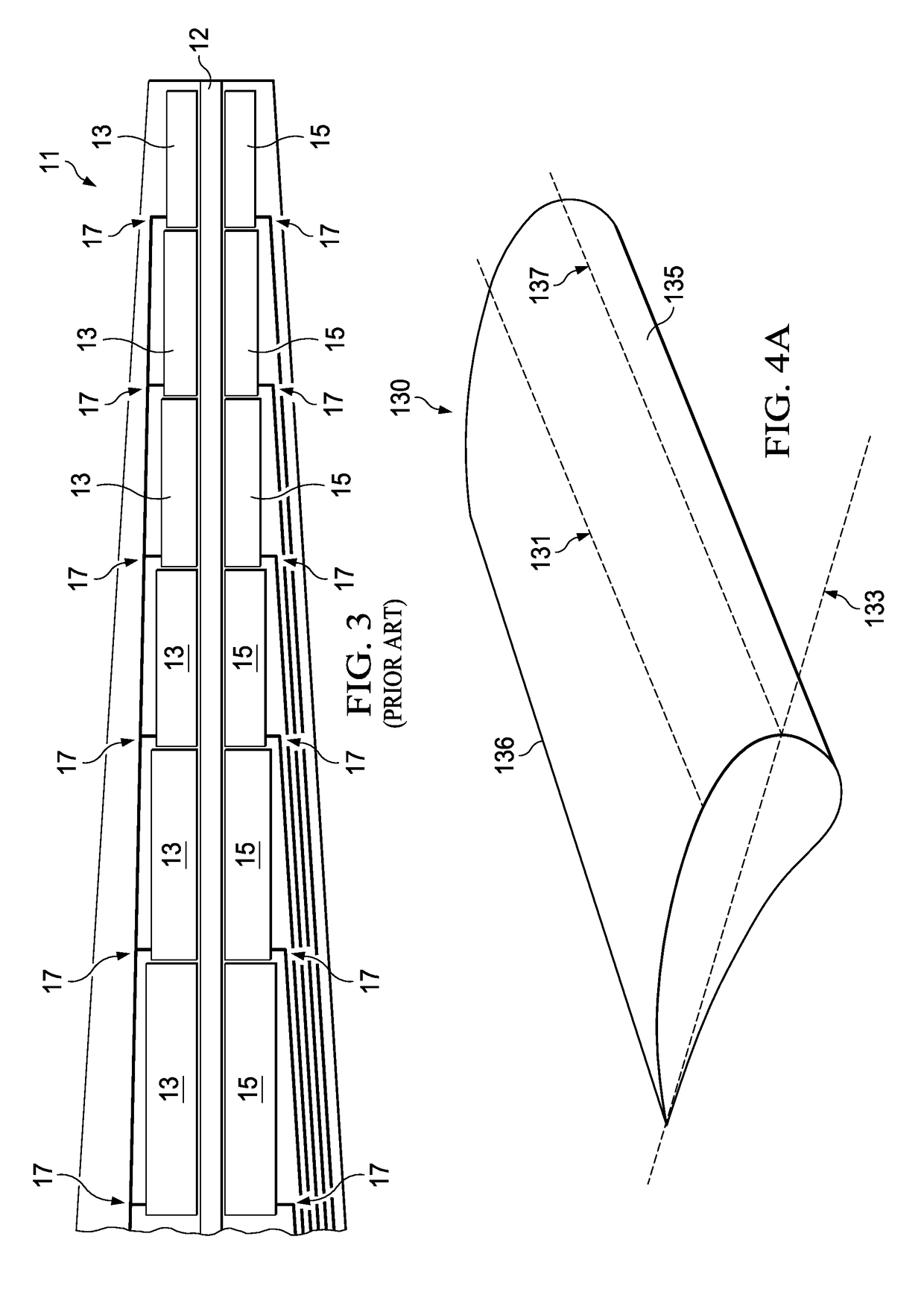
Another disadvantage to the chordwise zone configuration is the need to provide power to chordwise zones that are located outboard on the blade because it drives electrical bus bars to be routed aft of the heating zones down the span of the blade.
In this design, the bus bars are exposed to some of the highest strains on the blade which limits the options for material and design for the elements that perform this function.
There is typically at least one crossover wire for each chordwise zone and it is in these areas that there is an increased risk of shorting the anti-ice heating elements to the de-ice crossover wires.
In addition, internal structure of the leading edge of a rotor blade is very space-constrained and the great number of electrical connection can make it difficult to meet thickness requirements, which can result in high spots, resistance issues, and shorts within the rotor blade structure.
The prior configurations of rotor blade ice protection systems for a tiltrotor aircraft described above can result in a product that has poor reliability and is difficult to manufacture consistently with high quality.

Method used


Image

  • Ice protection system
  • Ice protection system
  • Ice protection system

Examples


Embodiment Construction

[0045]Illustrative embodiments of ice protection systems and methods of operation therefor are described below. In the interest of clarity, all features of an actual implementation may not be described in this specification. It will, of course, be appreciated that in the development of any such actual embodiment, numerous implementation-specific decisions must be made to achieve the developer's specific goals, such as compliance with system-related and business-related constraints, which will vary from one implementation to another. Moreover, it will be appreciated that such a development effort might be complex and time-consuming but would nevertheless be a routine undertaking for those of ordinary skill in the art having the benefit of this disclosure.

[0046]In the specification, reference may be made to the spatial relationships between various components and to the spatial orientation of various aspects of components as the devices are depicted in the attached drawings. However, ...


PUM


Abstract

There is provided an ice protection system for a rotary aircraft, including a rotor blade susceptible to an ice buildup having an inboard portion and an outboard portion, the length of the inboard portion and the length of the outboard portion define a total length of the rotor blade; a first deicing system coupled to the inboard portion of the rotor blade, the first deicing system including a plurality of spanwise zones; and a second deicing system coupled to the outboard portion of the rotor blade, the second deicing system including a plurality of chordwise zones. In one aspect, there is provided a deicing system for a rotary aircraft. In another aspect, there is a method to de-ice a rotor blade of an aircraft.

Description

BACKGROUNDTechnical Field[0001]The present disclosure relates to ice protection systems, and more particularly, to an ice protection system for rotary aircraft, such as a tiltrotor aircraft.Description of Related Art[0002]Vertical takeoff and landing aircraft (“VTOL”) can have ice-buildup that can negatively impact performance and cause catastrophic failure. One example of a VTOL aircraft is a tiltrotor. A tiltrotor aircraft may operate in a helicopter mode by positioning the nacelles upright, a transition mode by tilting the nacelles, and in an airplane mode by positioning the nacelles forward. Each propulsion system within a nacelle includes at least a proprotor, a gearbox, and a power source. The proprotor has a plurality of rotor blades that must operate over a wide range of speeds and angles in a variety of atmospheric conditions.[0003]Tiltrotor aircraft have ice-buildup vulnerabilities that do not exist on either propeller-driven, fixed-wing aircraft, or conventional helicopte...

Claims


Application Information

Patent Timeline
Patent Type & Authority Applications(United States)
IPC IPC(8): B64D15/14B64D15/22
CPCB64D15/14B64D15/22B64C29/0033B64D15/12
Inventor AUBERT, ROGER J.PAULSON, JARED M.
Owner BELL HELICOPTER TEXTRON INC
Why Eureka
Try Eureka