Automotive vehicle skid recovery system

a recovery system and automobility technology, applied in the direction of braking systems, way cleaning, construction, etc., can solve the problems of vehicle skid, decrease of friction, and failure of conventional braking systems for automotive vehicles

Active Publication Date: 2013-10-31
IBM CORP
View PDF50 Cites 10 Cited by
  • Summary
  • Abstract
  • Description
  • Claims
  • Application Information

AI Technical Summary

Benefits of technology

[0010]In another embodiment of the vehicle skid recovery system (VSRS), the ice remover can comprise a heater (e.g., a forced hot air heater, an infrared heater, a laser heater, etc.) mounted within the wheel well. In this case, the controller can be operably connected to the heater and, when the anti-lock braking system is activated and the temperature is below the threshold temperature, the controller can cause the heater to turn on and, particularly, can cause the heater to direct heat toward the road surface, thereby melting the ice that is on the road surface just forward of the wheel.

Problems solved by technology

Conventional braking systems for automotive vehicles tend to fail when road surface conditions are icy.
Specifically, when road conditions are icy, vehicles have a tendency to skid (i.e., slide) when the brakes are applied and, particularly, when they are applied suddenly.
As ice accumulation increases, friction decreases and skidding occurs.
Unfortunately, the above-mentioned safety measures still do not solve the problem.
Due to limited resources, oftentimes not all roads are maintained and, even when roads are designated for maintenance, maintenance crews may not be able to keep up with ever-worsening weather conditions.
Furthermore, while ABS ensures that the driver of a vehicle doesn't make matters worse, it does not accelerate skid recovery in the presence of ice accumulation.
In this case, the controller can be operably connected to the heater and, when the anti-lock braking system is activated and the temperature is below the threshold temperature, the controller can cause the heater to turn on and, particularly, can cause the heater to direct heat toward the road surface, thereby melting the ice that is on the road surface just forward of the wheel.

Method used


Image

  • Automotive vehicle skid recovery system
  • Automotive vehicle skid recovery system
  • Automotive vehicle skid recovery system

Examples


Embodiment Construction

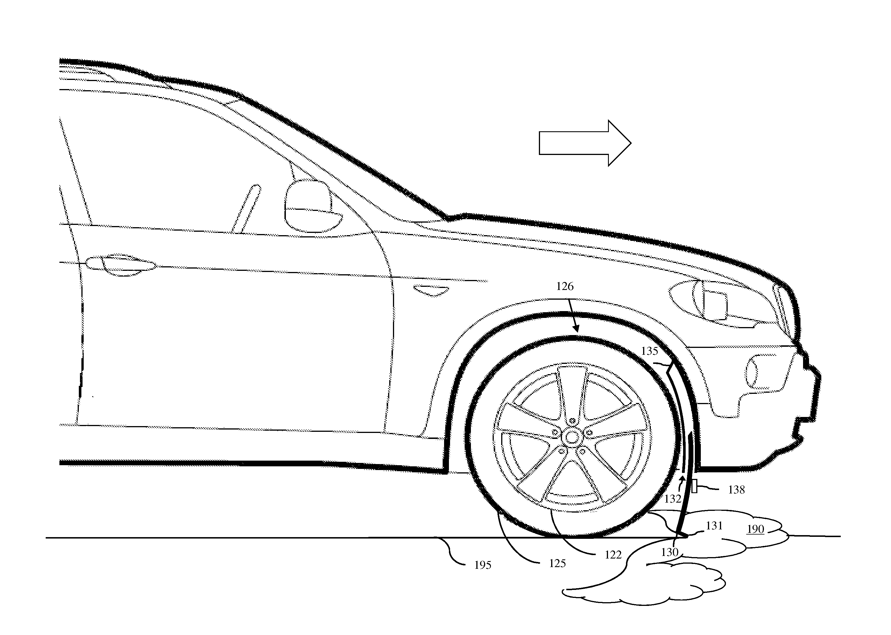
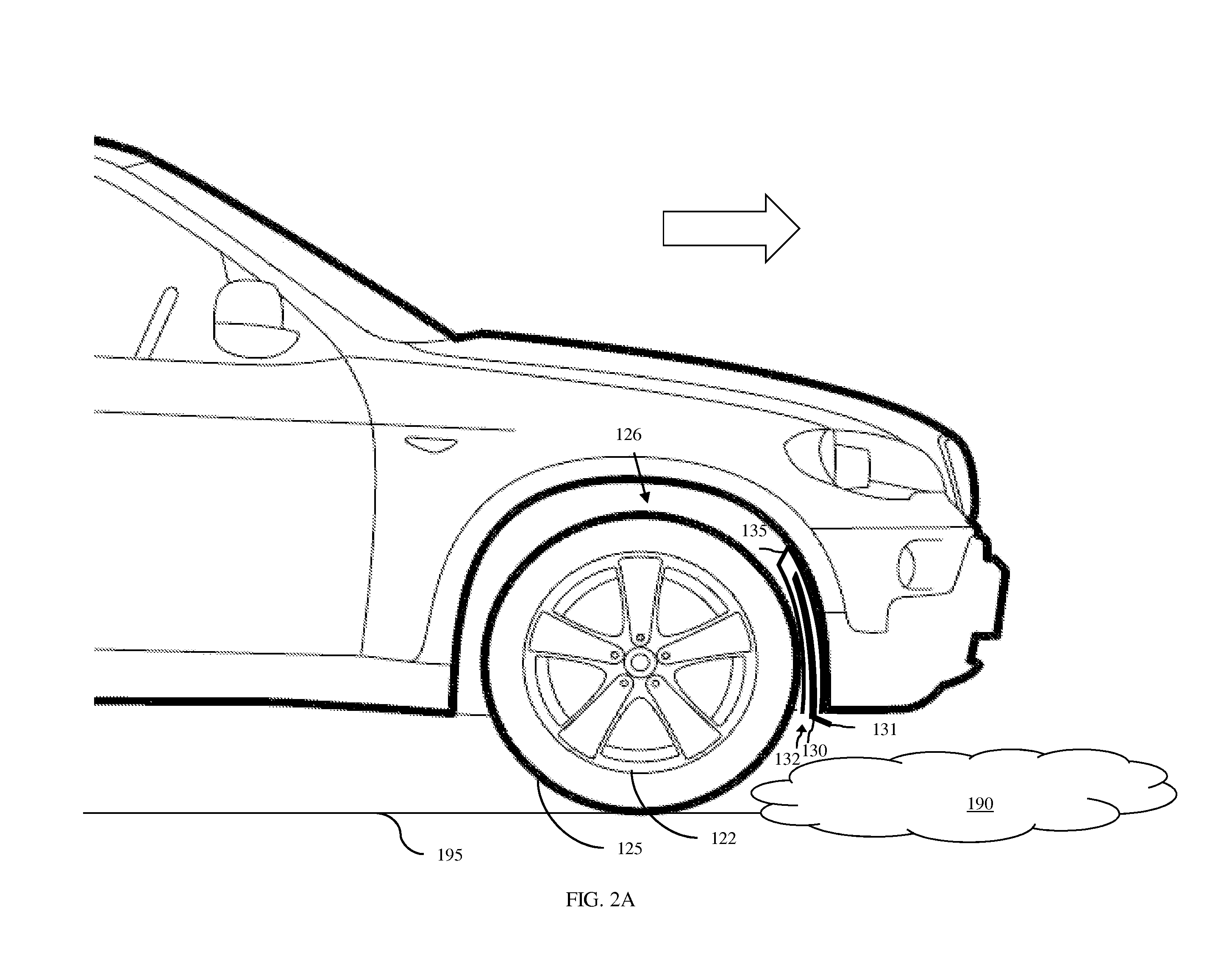
[0021]As mentioned above, conventional braking systems for automotive vehicles tend to fail when road surface conditions are icy. Specifically, when road conditions are icy, vehicles have a tendency to skid (i.e., slide) when the brakes are applied and, particularly, when they are applied suddenly. Such skidding, under icy conditions, is due to a low coefficient of friction between the tires of the vehicle and the road surface on which the vehicle is traveling. As ice accumulation increases, friction decreases and skidding occurs. For purposes of this disclosure, it should be understood that the term “automotive vehicle” refers to any self-propelled wheeled vehicle including, but not limited to, a car, a truck, a semi-truck, a sports utility vehicle, a van, a tractor, etc. Additionally, it should be understood that the term “ice” refers not only to solid ice, but also to any form of frozen precipitation containing ice particles such as snow, sleet, slush, hail, and freezing rain.

[00...


PUM


Abstract

Disclosed is a vehicle skid recovery system, which is able to accelerate skid recovery, when an automotive vehicle begins to skid as a result of ice accumulation on the road surface. The embodiments control operation of ice removers (e.g., blades or heaters), which are mounted within the wheel wells forward of the wheel, based on information received from the vehicle's outside temperature sensor and anti-lock braking system (ABS). When the temperature sensor indicates that the outside temperature is below a predetermined temperature (e.g., below freezing) and when the anti-lock braking system is activated as a result of detected skid, a controller activates the ice remover in one or more of the wheel wells and, thereby cause the ice remover to remove ice from the road surface forward of the corresponding wheel. Clearing the ice allows the vehicle's tires to gain traction on the road surface and, thereby stops the skid.

Description

BACKGROUND[0001]1. Field of the Invention[0002]The embodiments disclosed herein relate to automotive vehicle safety and, more particularly, to an automated system that assists with skid recovery, when an automotive vehicle begins to skid on an icy road surface.[0003]2. Description of the Related Art[0004]Conventional braking systems for automotive vehicles tend to fail when road surface conditions are icy. Specifically, when road conditions are icy, vehicles have a tendency to skid (i.e., slide) when the brakes are applied and, particularly, when they are applied suddenly. Such skidding, under icy conditions, is due to a low coefficient of friction between the tires of the vehicle and the road surface on which the vehicle is traveling. As ice accumulation increases, friction decreases and skidding occurs. For purposes of this disclosure, it should be understood that the term “automotive vehicle” refers to any self-propelled wheeled vehicle including, but not limited to, a car, a tru...

Claims


Application Information

Patent Timeline
Patent Type & Authority Applications(United States)
IPC IPC(8): E01H5/06B60T8/176E01H5/10
CPCB60T8/56E01H5/061E01H5/10B60T8/176B60T17/04E01H5/06
Inventor BORGES, GABRIEL P.CROWTHER, SCOTT R.GUERRA, ABRAHAM G.MILLER, GRANT D.NASSAR, NADER M.NASSAR, TAMER M.
Owner IBM CORP
Why Eureka
Try Eureka