Lane keeping assist system and lane keeping assist method

A lane keeping and assisting system technology, applied in vehicle components, transportation and packaging, driver input parameters, etc., can solve problems such as not considering the impact of longitudinal vehicles, easily causing traffic accidents, personal injuries, etc.

Active Publication Date: 2016-06-29
CHERY AUTOMOBILE CO LTD
View PDF10 Cites 113 Cited by
  • Summary
  • Abstract
  • Description
  • Claims
  • Application Information

AI Technical Summary

Problems solved by technology

[0006] At the same time, these existing lane keeping assist systems only consider that the lateral direction of the vehicle is kept within the left and right lane markings, which is considered safe, and does not consider the impact of longitudinal vehicles, which poses a great safety risk
For example, if there is a vehicle decelerating ahead in the lane where the vehicle is located, or another vehicle driving in the adjacent lane suddenly changes lanes to the lane where the vehicle is located and is in front of the vehicle, if the vehicle continues to perform lane keeping at this time, it may Colliding with the vehicle in front may easily cause a traffic accident or cause personal injury
In addition, the rolling friction coefficient between the driving vehicle and the road surface is constantly changing. In the theoretical calculation and practical application of the existing lane keeping assist system, it is simplified as a constant. When encountering rain, snow, icy weather and When the friction coefficient of the road surface or local road surface changes greatly due to other reasons, the way the existing lane keeping assist system handles the friction coefficient will directly affect the effect of the lane keeping system, which may cause misjudgment.
Therefore, the lane keeping assist system in the prior art has not achieved the purpose of lane keeping assist control with high precision, high intelligence and high safety.

Method used


Image

  • Lane keeping assist system and lane keeping assist method
  • Lane keeping assist system and lane keeping assist method
  • Lane keeping assist system and lane keeping assist method

Examples


Embodiment Construction

[0051] The technical solution of the present invention will be described in detail below in conjunction with the accompanying drawings, so that those skilled in the art can understand the solution of the present invention more clearly, but the protection scope of the present invention is not limited thereby.

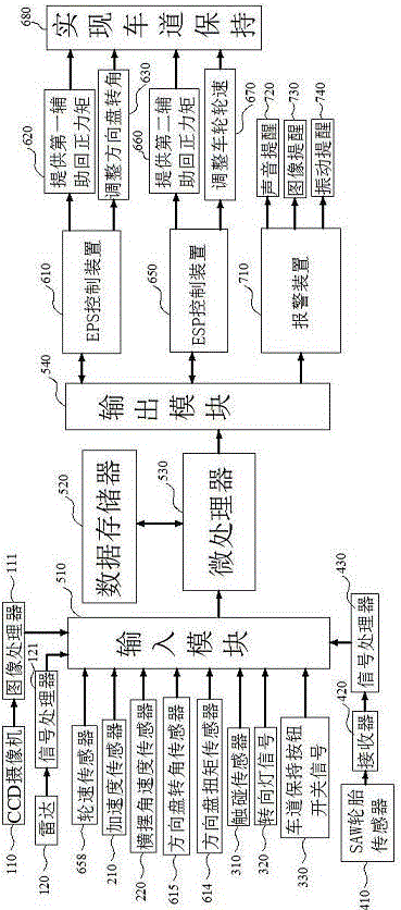
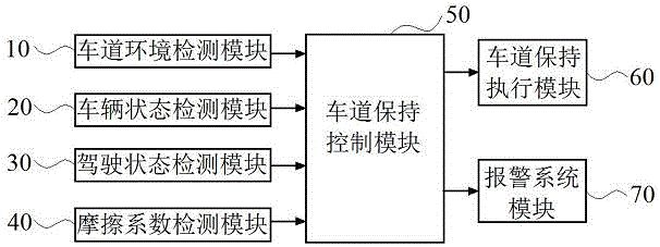
[0052] figure 1It is a schematic diagram of the module structure of the lane keeping assist system of the present invention. As shown in the figure, the lane keeping assist system consists of a lane environment detection module 10, a vehicle state detection module 20, a driver driving state detection module 30, a vehicle and road surface rolling friction coefficient detection module 40, a lane keeping control module 50, a lane The maintenance execution module 60 and the alarm system module 70 are composed of seven parts. The lane environment detection module 10, the vehicle state detection module 20, the driver's driving state detection module 30, and the vehicle and ro...


PUM


Abstract

The invention proposes a lane keeping assist system and a lane keeping assist method. The method comprises the steps of comprehensively detecting a people-vehicle-road driving environment through a lane environment detection module, a vehicle state detection module, a driver driving state detection module and a vehicle and road surface rolling friction coefficient detection module; calculating a corresponding detection signal through a lane keeping control module; judging whether a vehicle deviates from a lane or not; performing transverse lane return-to-center control through cooperative control of an electric power steering system (EPS) and an electronic stability program (ESP), and keeping a longitudinal safety distance through ESP control; and giving an alarm for reminding. Through the technical scheme provided by the invention, the driving safety of vehicle driving is remarkably improved; and the lane keeping is realized through the cooperative control of the EPS and the ESP, so that on the premise of ensuring the driving safety of the vehicle, the working comfort of the lane keeping assist system can be improved to the maximum extent.

Description

technical field [0001] The invention relates to the field of safe driving of automobiles, in particular to a lane keeping assisting system and a lane keeping assisting method suitable for motor vehicles. Background technique [0002] Lane Keeping Assist System (LaneKeepingAssistSystem: LKAS) refers to an intelligent driving assistance system that prevents the vehicle from leaving the lane by controlling the vehicle when it is predicted that the vehicle will leave the lane based on the driving information and road information of the driving vehicle. Its important function is to assist the driver who is overtired or monotonously driving for a long time to keep the vehicle in the lane in high-speed or similar highway environment, so as to improve the safety of the vehicle. [0003] In the prior art, the invention patents CN1244034C, CN100469630C, and CN101965286B have the idea of ​​controlling the braking force or driving force acting on each wheel according to the lateral move...

Claims


Application Information

Patent Timeline
Patent Type & Authority Applications(China)
IPC IPC(8): B60W30/12B60W10/184B60W10/20B60W50/14
CPCB60W10/184B60W10/20B60W30/12B60W50/14B60W2050/143B60W2050/146B60W2520/105B60W2520/125B60W2520/14B60W2520/28B60W2540/20B60W2552/40B60W2554/00B60W2554/4041B60W2554/801B60W2555/60
Inventor 李龙刚刘春玲李朋龙刘慧建裴福兴
Owner CHERY AUTOMOBILE CO LTD
Why Eureka
Try Eureka