Apparatus and method for object detection and tracking and roadway awareness using stereo cameras

a stereo camera and object detection technology, applied in scene recognition, instruments, brake systems, etc., can solve the problems of severe inhibition of the ability to reflect light back to the laser-based sensor, the disadvantage of radar-based sensors over laser-based sensors is their cost, and achieve the effect of reducing the cost of sensory based components and improving the performance of vehicle detection and tracking

Active Publication Date: 2007-11-01
ZAMA INNOVATIONS LLC
View PDF20 Cites 111 Cited by
  • Summary
  • Abstract
  • Description
  • Claims
  • Application Information

AI Technical Summary

Benefits of technology

[0010] In view of the foregoing, it is an object of the present invention to provide a collision avoidance system enabled by input of a scene image received solely from a vision-based stereo configuration, thereby eliminating costly sensory based components and providing a performance-enhanced approach to vehicle detection and tracking.
[0011] It is another object of the present invention to provide a collision avoidance system enabled to receive a focused estimation of three dimensional structures and regions, as well as detailed scene context relating to the immediate headway of a vehicle.
[0012] It is yet another object of the present invention to provide a collision avoidance system enabled with a means for rejecting spurious scene image data and increasing system reliability.
[0016] The most visible advantages of the present invention is that of performance and cost. The integration of stereo vision sensing in the present invention provides a more reliable three-dimensional estimation of a target vehicle structure than a monocular system alone, and can provide more scene context than a radar system alone. Moreover, it is less costly than the combination of an ACC radar and a monocular vision system, and offers a more straightforward integration solution than a multi-sensor system.

Problems solved by technology

Radar-based sensors also perform better when used on target vehicles that are extremely dirty (which severely inhibits the ability to reflect light back to the laser-based sensor).
However, a considerable disadvantage of radar-based sensors over laser-based sensors is their cost.

Method used


Image

  • Apparatus and method for object detection and tracking and roadway awareness using stereo cameras
  • Apparatus and method for object detection and tracking and roadway awareness using stereo cameras
  • Apparatus and method for object detection and tracking and roadway awareness using stereo cameras

Examples


Embodiment Construction

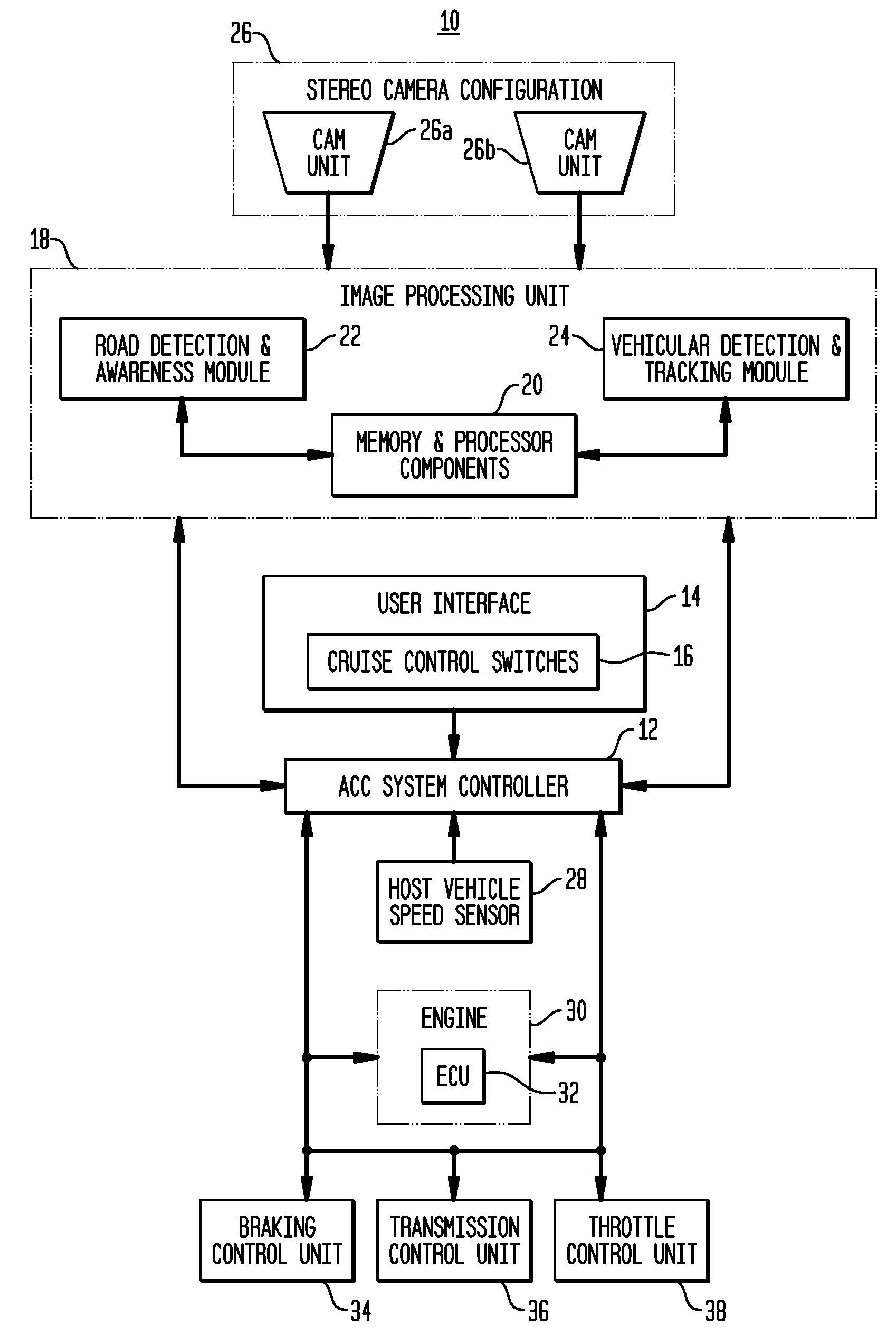
[0038] The present invention is directed towards an apparatus and method for enabling adaptive vehicular systems employing solely the use of stereo cameras for detection and tracking applications. For purposes of clarity, and not by way of limitation, illustrative views of the present invention are described herein with references being made to the aforementioned drawing figures. The following detailed description in conjunction with the referenced figures are provided to enable and assist in the understanding of the present invention and, as such, the drawing figures should not be deemed to be exhaustive of all the various modifications obvious to one skilled in the art. Such obvious modifications are deemed to be well within the spirit and scope of the present invention.

[0039] An autonomous collision avoidance apparatus 10 is illustrated in FIG. 1. In accordance with a preferred embodiment of the present invention, an adaptive cruise control (ACC) system is depicted in connection...


PUM


Abstract

The present invention provides a collision avoidance apparatus and method employing stereo vision applications for adaptive vehicular control. The stereo vision applications are comprised of a road detection function and a vehicle detection and tracking function. The road detection function makes use of three-dimensional point data, computed from stereo image data, to locate the road surface ahead of a host vehicle. Information gathered by the road detection function is used to guide the vehicle detection and tracking function, which provides lead motion data to a vehicular control system of the collision avoidance apparatus. Similar to the road detection function, stereo image data is used by the vehicle detection and tracking function to determine the depth of image scene features, thereby providing a robust means for identifying potential lead vehicles in a headway direction of the host vehicle.

Description

CROSS-REFERENCE TO RELATED APPLICATIONS [0001] This application claims the benefit of U.S. Provisional Patent Application No 60 / 794,064, filed Apr. 21, 2006, which is hereby incorporated by reference in its entirety.BACKGROUND OF THE INVENTION [0002] 1. Field of the Invention [0003] The present invention relates generally to a stereopsis-based application. More particularly, the present invention is directed to an apparatus and method for detecting and tracking objects within corresponding detected roadway features utilizing a stereo vision configuration, thereby enabling and improving applications in autonomous systems for vehicular control. [0004] 2. Description of the Related Art [0005] Developments in the field of computer vision and the availability of processors with increased processing speeds and multitasking capabilities have led to new and improved video-based technologies, but it has not been until only in the past few years that these developments have begun to appear in...

Claims


Application Information

Patent Timeline
Patent Type & Authority Applications(United States)
IPC IPC(8): B60T7/12G08G1/16
CPCB60T7/22B60T2201/089B60W30/08B60W30/095B60W30/16B60W2420/403G06K9/00825G06T7/0075G06T7/2086G08G1/16G08G1/167G06K9/00798G06K9/00805G06K9/00201G06T7/593G06T7/285G06V20/64G06V20/588G06V20/58G06V20/584
Inventor SOUTHALL, JOHN BENJAMINBANSAL, MAYANKJAIN, AASTHAKUMAR, MANISHCAMUS, THEODORE ARMANDDAS, AVEEK KUMARFIELDS, JOHN RICHARDGREENE, GARY ALANELEDATH, JAYAKRISHNAN
Owner ZAMA INNOVATIONS LLC
Why Eureka
Try Eureka