Virtual ice accretion meter display

a virtual ice accretion and display technology, applied in surveying and navigation, navigation instruments, instruments, etc., can solve problems such as affecting the flying characteristics of aircraft, affecting the flight characteristics of aircraft, and forming i

Inactive Publication Date: 2011-09-22
SIKORSKY AIRCRAFT CORP
View PDF49 Cites 11 Cited by
  • Summary
  • Abstract
  • Description
  • Claims
  • Application Information

AI Technical Summary

Problems solved by technology

Aircraft may encounter atmospheric conditions that may cause the formation of ice.
Accumulated ice, if not removed, may add weight to the aircraft and may alter the ai

Method used


Image

  • Virtual ice accretion meter display
  • Virtual ice accretion meter display
  • Virtual ice accretion meter display

Examples


Embodiment Construction

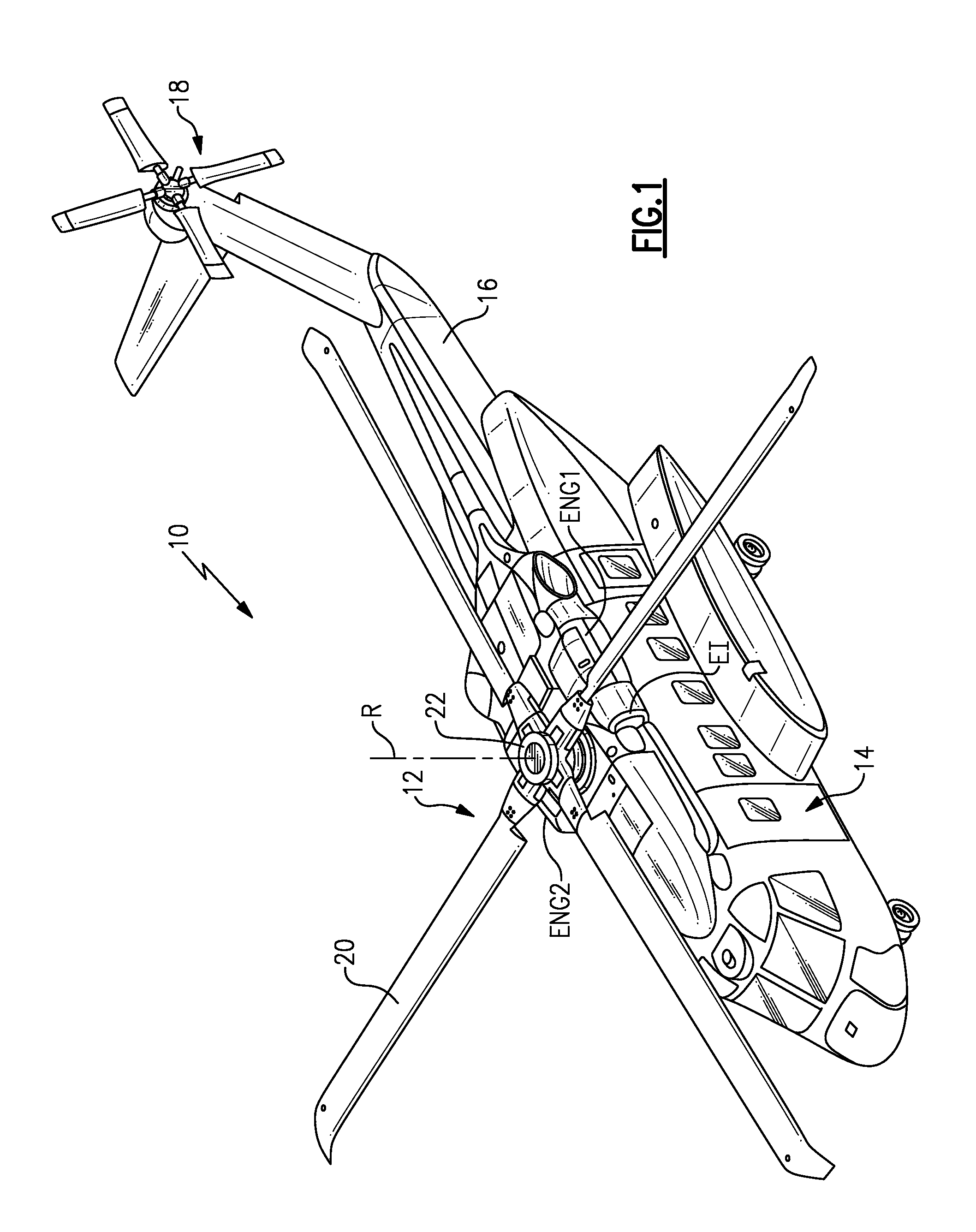
[0015]FIG. 1 schematically illustrates an exemplary vertical takeoff and landing (VTOL) rotary-wing aircraft 10. The aircraft 10 in the disclosed, non-limiting embodiment includes a main rotor system 12 supported by an airframe 14 having an extending tail 16 which mounts an antitorque system 18 such as a tail rotor system. The main rotor system 12 is driven about an axis of rotation R through a main gearbox MRG by one or more engines ENG1, ENG2. An engine inlet EI directs air to the engines ENG1 and ENG2. The main rotor system 12 includes a multiple of rotor blades 20 mounted to a rotor hub 22. Although a particular VTOL rotary-wing aircraft configuration is illustrated and described in the exemplary embodiment, other configurations and / or machines, such as high speed compound rotary wing aircraft with supplemental translational thrust systems, dual contra-rotating, coaxial rotor system aircraft, fixed wing aircraft, VTOL aircraft, turbo-props, tilt-rotors and tilt-wing aircraft, wi...


PUM


Abstract

A flight display for an aircraft includes a virtual ice accretion meter having a liquid water content portion and an ice thickness portion. A method for determining ice accretion includes integrating over a time period a constant K multiplied by a liquid water content (LWC) and true airspeed (TAS).

Description

REFERENCE TO RELATED APPLICATIONS[0001]The present application claims the benefit of U.S. Provisional Patent Application No. 61 / 314741, filed Mar. 17, 2010.BACKGROUND[0002]The present disclosure relates to an aircraft flight display, and more particularly to a virtual ice accretion meter display with an ice thickness display portion.[0003]Aircraft may encounter atmospheric conditions that may cause the formation of ice. Accumulated ice, if not removed, may add weight to the aircraft and may alter the aircraft flying characteristics.[0004]Many rotary-wing aircraft and low-speed fixed-wing aircraft utilize an ice accretion device to measure the cumulative effect of flight through an icing cloud. This ice accretion device, frequently referred to as a Visual Accretion Meter (VAM), protrudes from the aircraft fuselage in view of the aircrew. The aircrew visually gage the total effect of an icing environment through indicating marks on the device. The device typically includes an illumina...

Claims


Application Information

Patent Timeline
IPC IPC(8): B64D15/20
CPCG01C23/005B64D15/20
Inventor FLEMMING, ROBERT JAMES
Owner SIKORSKY AIRCRAFT CORP
Why Eureka
Try Eureka