Takedown Assembly For Assault Rifle

a rear-mounted and assault rifle technology, applied in the direction of breech mechanism, weapon components, breech mechanisms, etc., can solve the problems of user accidental misplacement of rear takedown pins, process flaws,

Active Publication Date: 2018-03-08
VITESCO TECH USA LLC
View PDF11 Cites 4 Cited by
  • Summary
  • Abstract
  • Description
  • Claims
  • Application Information

AI Technical Summary

Problems solved by technology

However, this process has its flaws.
A user can accidentally misplace the rear takedown pin.

Method used


Image

  • Takedown Assembly For Assault Rifle
  • Takedown Assembly For Assault Rifle
  • Takedown Assembly For Assault Rifle

Examples


Embodiment Construction

[0035]The claimed subject matter is now described with reference to the drawings. In the following description, for purposes of explanation, numerous specific details are set forth in order to provide a thorough understanding of the claimed subject matter. It may be evident, however, that the claimed subject matter may be practiced with or without any combination of these specific details, without departing from the spirit and scope of this invention and the claims.

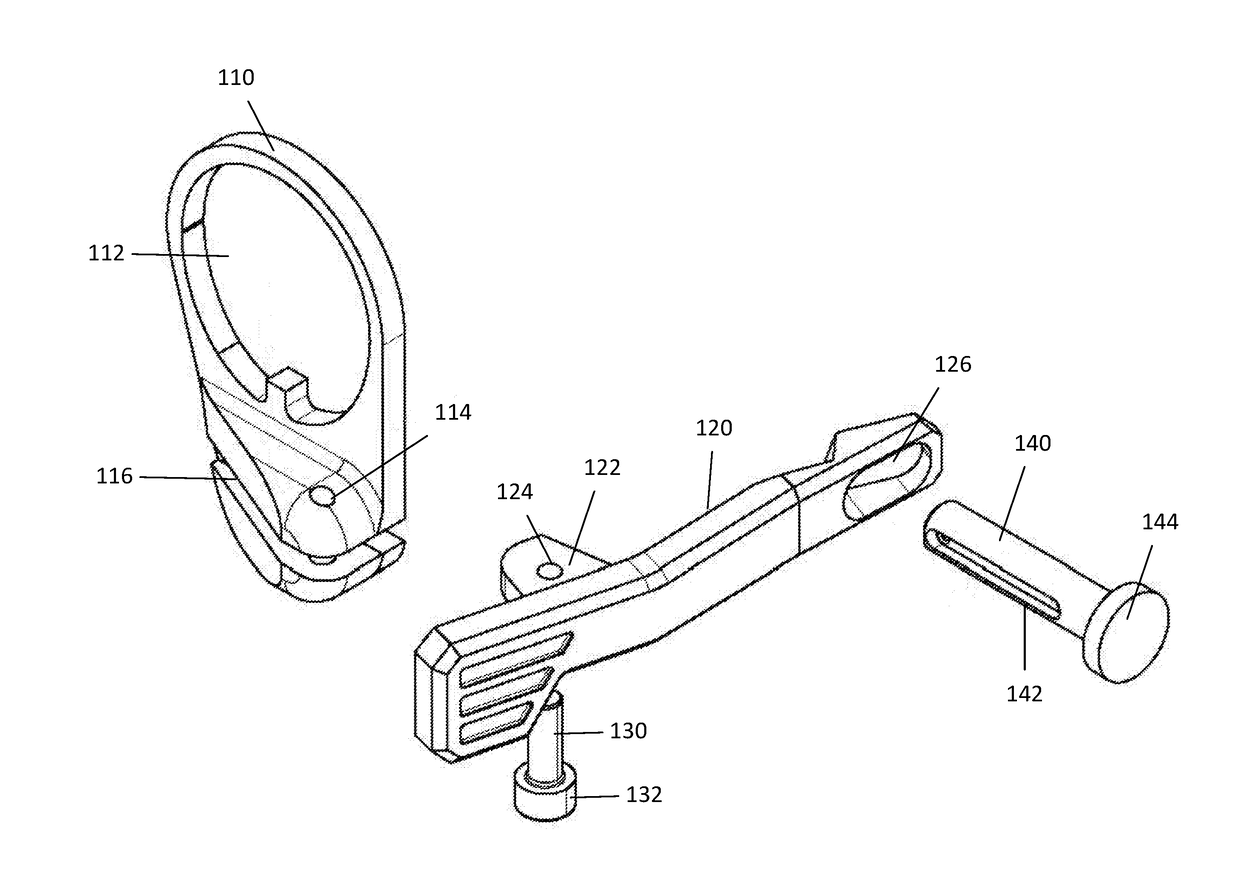
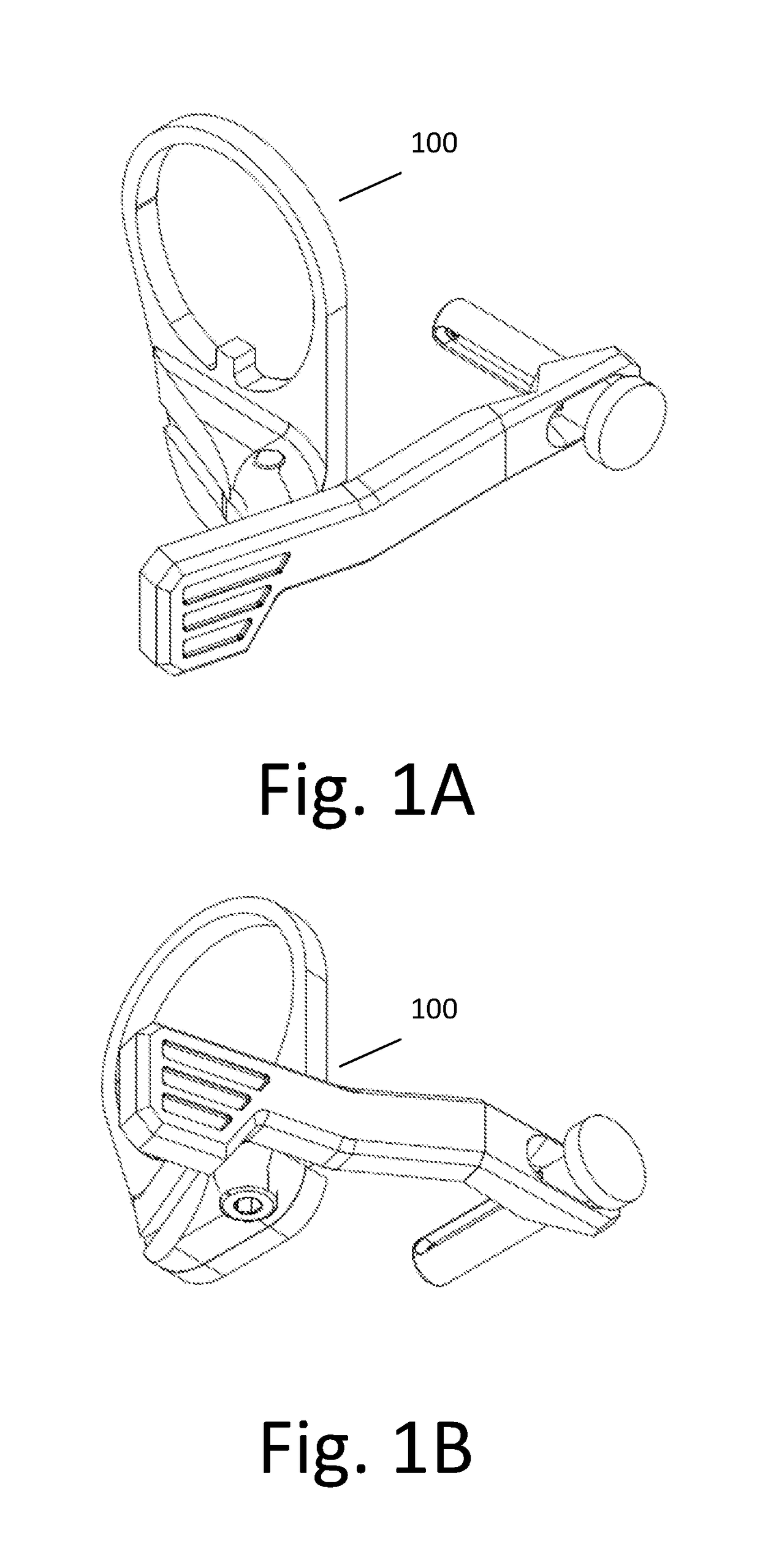
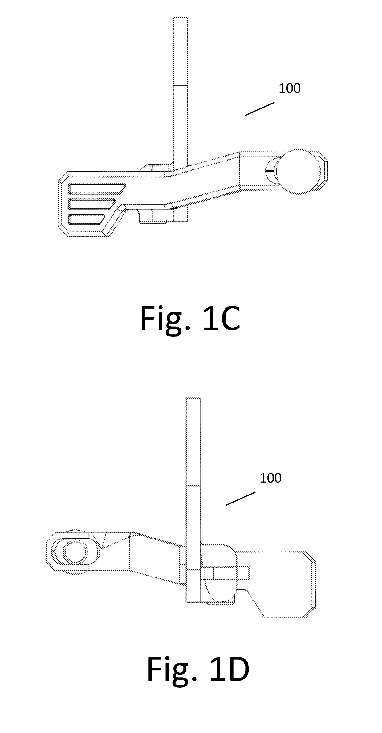
[0036]Referring to FIG. 1A-FIG. 6, the preferred embodiment of the invention is displayed. The invention is directed toward a rear mounted takedown assembly 100. The takedown assembly 100 may come in any configuration which permits a rear takedown pin to be removed and reinserted into the upper and lower receiver of the firearm. In the preferred embodiment the takedown assembly 100 comprises a docking plate 110, a lever 120, a pivot pin 130, and a takedown pin 140.

[0037]Referring to FIGS. 3-6, the separate components of t...


PUM


Abstract

The present invention is directed toward a firearm takedown assembly. The preferred embodiment of the firearm takedown assembly comprises a docking plate configured to be removably secured to a firearm and a lever pivotably attached to the docking plate. The assembly may further comprise a pivot pin, wherein the lever is connected to the pivot pin. The lever is utilized to remove a takedown pin from the upper and lower receiver of the firearm so that a user may quickly disassembly the firearm. When the user desires to reassembly the user may thumb the lever to reinsert the takedown pin into the upper and lower receiver.

Description

PRIORITY[0001]This application claims priority to U.S. Provisional Patent Application Ser. No. 62 / 384,168, filed Sep. 6, 2016, the disclosure of which is hereby incorporated by reference.FIELD OF THE INVENTION[0002]The invention is directed to a firearm accessory and more specifically to a rear mounted takedown assembly for an assault rifle which permits the quick and easy separation and unification of a top receiver and lower receiver of an assault rifle.BACKGROUND OF INVENTION[0003]Semi-automatic firearms have been known for a long time. The first semi-automatic rifle was introduced in 1885. The M-16 automatic rifle has been used by the military for years. A civilian version of the M-16 is known as the AR-15 and is a semi-automatic rifle. The AR-15 has been manufactured and sold to civilians for many years. Standard AR-15 semi-automatic rifles are manufactured and distributed with an upper receiver and a lower receiver. The upper receiver and lower receiver are normally attached t...

Claims


Application Information

Patent Timeline
Patent Type & Authority Applications(United States)
IPC IPC(8): F41A11/00F41A3/66F41A3/84
CPCF41A11/00F41A3/84F41A3/66
Inventor KLEIN, TRAVISMCCURDY, BART
Owner VITESCO TECH USA LLC
Why Eureka
Try Eureka