Mechanical system for transmitting motion and an aircraft fitted with a corresponding system

Active Publication Date: 2018-03-15
EUROCOPTER
View PDF0 Cites 0 Cited by
  • Summary
  • Abstract
  • Description
  • Claims
  • Application Information

AI Technical Summary

Benefits of technology

The present invention provides a mechanical system that is not affected by the limitations of conventional bevel gear sets. This system is designed to reduce weight and cost while maintaining long life and reliability. The system achieves a speed reduction ratio directly without requiring an additional speed reduction member. The arrangement of the axes in the system makes it easier to design the drivetrain of a machine or vehicle with the system fitted thereto. The first, second, and third axes may be coplanar, which simplifies the design of the drivetrain for transmitting rotary motion between the various axes.

Problems solved by technology

Such a mechanical system thus goes against the theory normally used by the person skilled in the art for designing bevel gear sets, but it makes it possible to limit weight and cost very significantly, while nevertheless not compromising long life and reliability.

Method used


Image

  • Mechanical system for transmitting motion and an aircraft fitted with a corresponding system
  • Mechanical system for transmitting motion and an aircraft fitted with a corresponding system
  • Mechanical system for transmitting motion and an aircraft fitted with a corresponding system

Examples


first embodiment

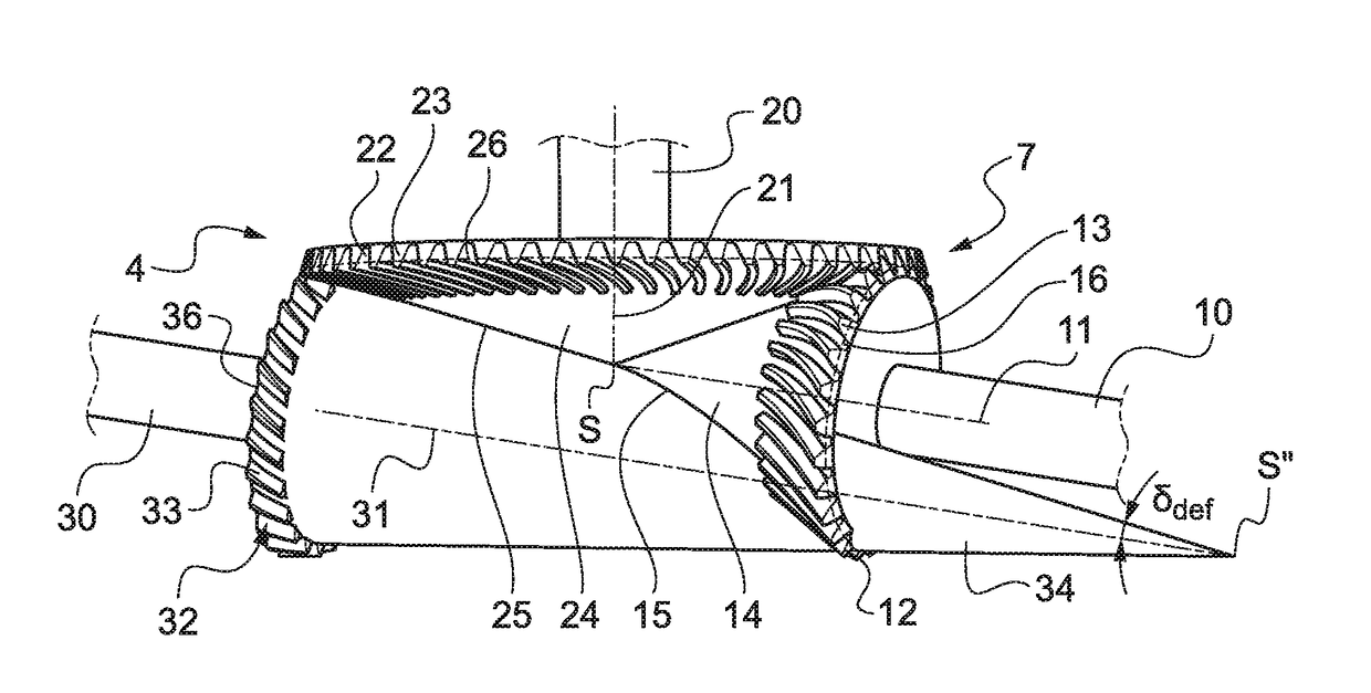
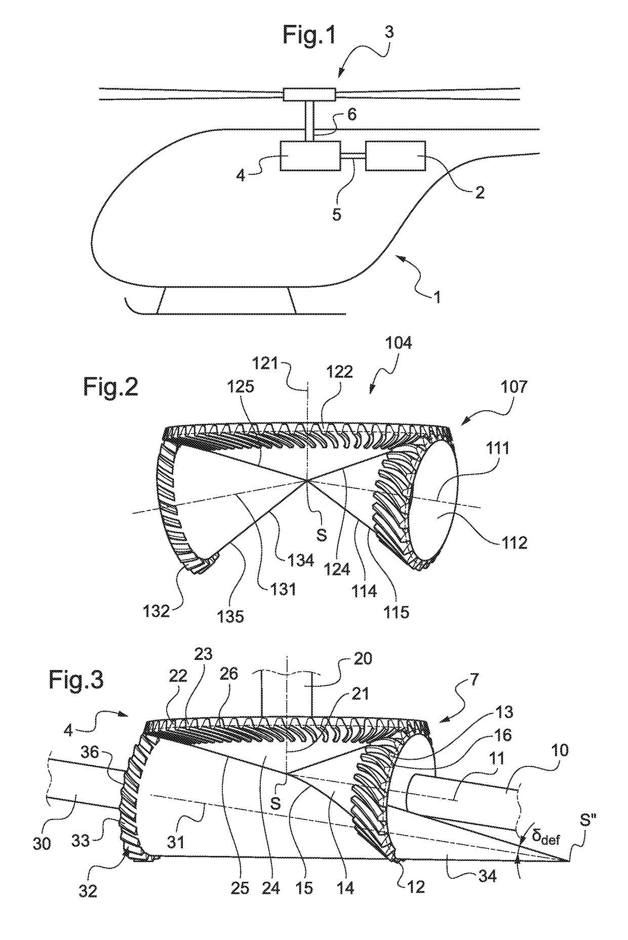
[0047]As shown in FIGS. 3 to 5, in a first embodiment, the mechanical transmission system 4 enables rotary motion to be transmitted between a first shaft 10 and a second shaft 20. The shafts 10 and 20 are movable in rotation about respective first and second mutually intersecting axes 11 and 21.

[0048]The mechanical system 4 has a bevel gear set 7 including a first bevel gear 12, referred to as the “power” gear, and that has teeth 13. Such a power gear 12 is then movable in rotation about a first axis 11. The bevel gear set 7 then also has a bevel wheel 22 that has teeth 23. The bevel wheel 22 is movable in rotation about a second axis 21.

[0049]The respective teeth 13 and 23 of the first power gear 12 and of the bevel wheel 22 may be of straight shape or of helical shape, and they are suitable for co-operating in complementary manner with one another. Also, the power gear 12 presents a first defining pitch surface 14 of conical shape while the bevel wheel 12 presents a second definin...

second embodiment

[0064]As shown in FIG. 7, the mechanical transmission system 4′ has a bevel gear set 7′ including a power gear 12′. Such a power gear 12′ is then movable in rotation about a first axis 11′. The bevel gear set 7′ then also includes a bevel wheel 22′. The bevel wheel 22′ is movable in rotation about a second axis 21′.

[0065]Such a mechanical system 4′ also includes an accessory gear 32′ driven in rotation by the bevel wheel 22′, such an accessory gear 32′ being movable in rotation about a third axis 31′.

[0066]As shown, the first, second, and third axes 11′, 21′, and 31′ are arranged in mutually non-coplanar manner and thus allow the angular orientation of the rotary motion transmitted by such a mechanical system 4′ to be modified.


PUM


Abstract

A mechanical system for transmitting rotary motion between at least two shafts movable in rotation respectively about a first axis and a second axis, the first and second axes intersecting, the mechanical system including a bevel gear set made up of a first bevel gear having teeth and movable in rotation about the first axis and a bevel wheel having teeth and movable in rotation about the second axis, the teeth of the first bevel gear and of the bevel wheel respectively being suitable for co-operating in complementary manner with one another, the first bevel gear, referred to as a “power” gear, presenting a first defining pitch surface of conical shape, and the bevel wheel presenting a second defining pitch surface of conical shape.

Description

CROSS-REFERENCE TO RELATED APPLICATIONS[0001]This application claims priority to French patent application No. FR 16 01331 filed on Sep. 9, 2016, the disclosure of which is incorporated in its entirety by reference herein.BACKGROUND OF THE INVENTION(1) Field of the Invention[0002]The present invention relates to the field of means for transmitting rotary motion between at least two shafts.[0003]More particularly, the invention relates to a mechanical system including a bevel gear set in a main drivetrain for transmitting driving torque and an additional accessory gear co-operating with a bevel wheel of the bevel gear set.(2) Description of Related Art[0004]In known manner, mechanical systems of this type are designed to limit slip and wear between the various teeth of each of the gears and the bevel wheel. In order to guarantee such a result, the respective axes of rotation must necessarily be arranged relative to one another so that all three of them intersect at a point. Furthermo...

Claims


Application Information

Patent Timeline
IPC IPC(8): B64C27/14F16H37/08F16H1/22
CPCB64C27/14B64D35/00F16H1/222F16H37/0826B64C27/12F16H57/023F16H2057/02039F16H55/0813F16H1/14B64C2027/125F16H55/17
Inventor DE MEERSCHMAN, OLIVIERGATTI, MATTHIAS
Owner EUROCOPTER
Why Eureka
Try Eureka