
Information presentation apparatus

a technology of information presentation and apparatus, which is applied in the direction of traffic control systems, transportation and packaging, instruments, etc., can solve the problems of difficult to attract the attention of the driver to an important risk target, and no process is performed for calculating the risk level of each risk target requiring the attention of the driver

Active Publication Date: 2018-03-29
DENSO CORP
View PDF37 Cites 58 Cited by
  • Summary
  • Abstract
  • Description
  • Claims
  • Application Information

AI Technical Summary

Benefits of technology

The present invention aims to provide an information presentation apparatus that can effectively grab a driver's attention towards an important risk target, even in a scenario where multiple risk targets are detected. The apparatus prioritizes the attention towards risk targets with a high risk level and grabs the driver's attention accordingly. This helps to accurately direct the driver's attention towards the important risk target, improving safety on the road.

Problems solved by technology

According to the vehicle display device disclosed in Patent Literature 1, however, no process is performed for calculating a risk level of each risk target requiring attention of the driver.
In this case, however, it may become difficult to attract attention of the driver to an important risk target.

Method used


Image

  • Information presentation apparatus
  • Information presentation apparatus
  • Information presentation apparatus

Examples


first embodiment

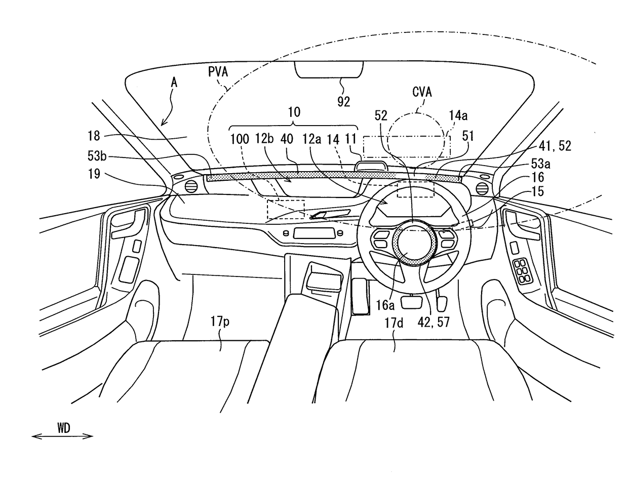
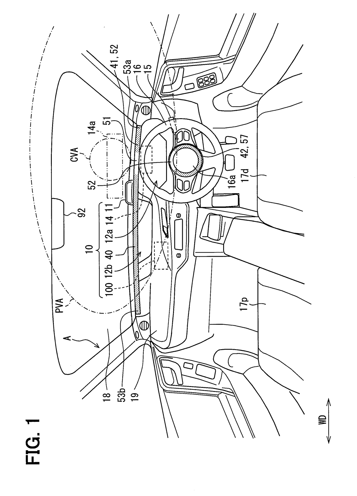
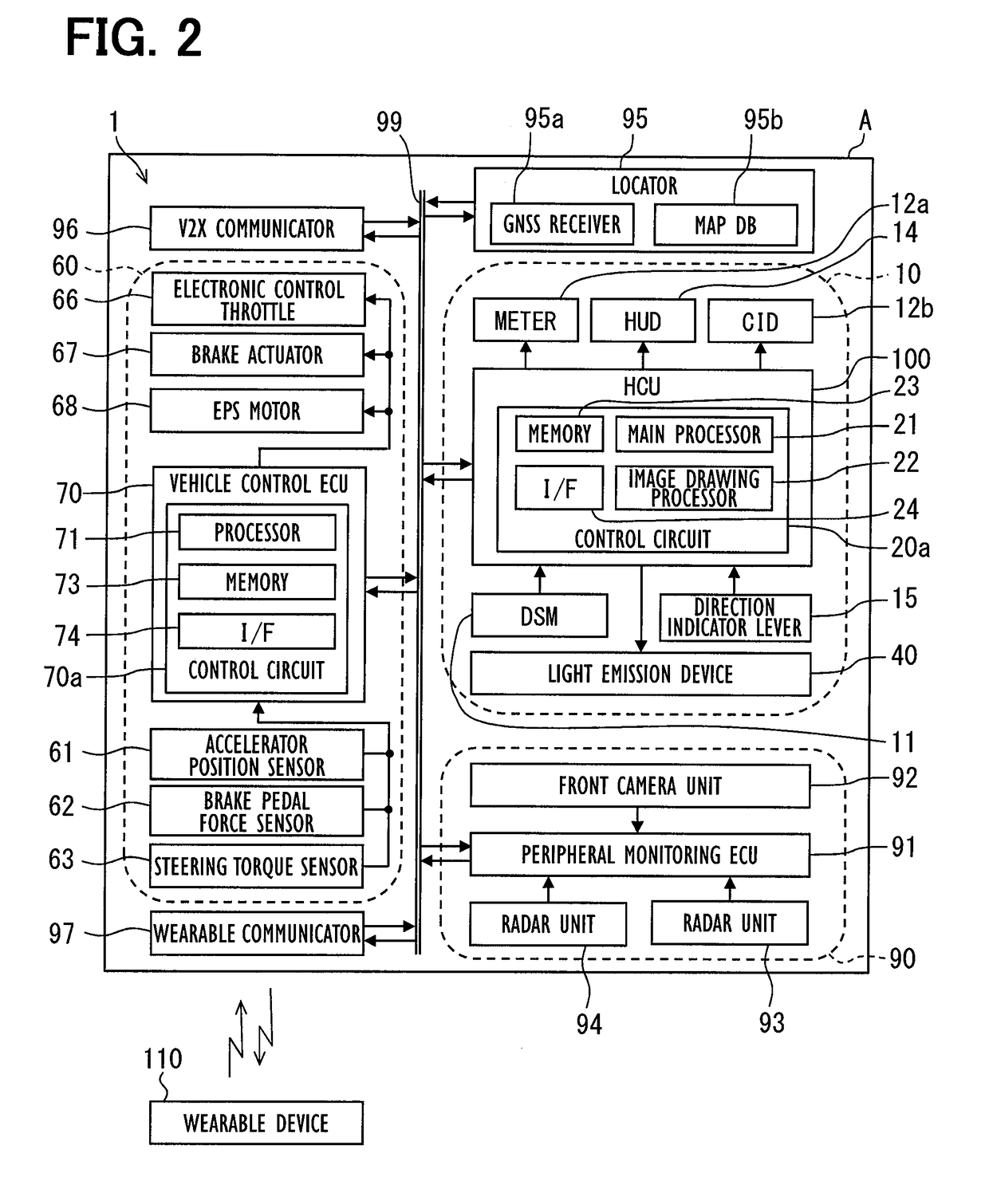
[0048]As illustrated in FIGS. 1 and 2, a human machine interface (HMI) control unit (HCU) 100 according to a first embodiment is an electronic device mounted on a self-vehicle A. The HCU 100 constitutes one of a plurality of nodes included in a vehicle onboard network 1. The vehicle onboard network 1 is configured by an external recognition system 90, a locator 95, a V2X communicator 96, a vehicle control system 60, a wearable communicator 97, an HMI system 10, a communication bus 99 to which these components are connected, and others.

[0049]The external recognition system 90 includes external sensors such as a front camera unit 92 and radar units 93 and 94, and a peripheral monitoring electronic control unit (ECU) 91 to detect a risk target requiring attention of the driver. More specifically, the external recognition system 90 detects a moving object such as a pedestrian, an animal other than a human, a bicycle, a motorcycle, and other vehicles, and further detects a stationary obj...

second embodiment

[0189]A second embodiment is a modified example of the first embodiment. In a risk target warning mode of the second embodiment, display of the instrument panel light emission line 41 is controlled without the use of visual line information about the driver. Accordingly, the DSM 11, the wearable device 110, and the wearable communicator 97 shown in FIG. 2 are unnecessary.

[0190]According to the configuration described above, the light emission control unit 34 (see FIG. 5) displays, in the linear light emission area 52, the light emission spot 51 indicating a direction of a highest risk target newly selected at the time of a change of a current highest risk target (see t4 in FIG. 27) in a scene where a plurality of risk targets are detected. In addition, display of the light emission spot 51 indicating the direction of the risk target which does not show the highest risk level any longer is ended after display of the light emission spot 51 indicating the direction of a newly selected ...


PUM


Abstract

An information presentation apparatus is provided. A light emission device and a HCU are mounted on a vehicle as the information presentation apparatus. The light emission device is arranged on an instrument panel, and displays at least one light emission spot in a linear light emission area arranged to extend in a width direction of the vehicle. The HCU acquires monitoring information including at least position information of the risk target detected by the peripheral monitoring device, and calculates a risk level of the risk target, detected in a traveling direction of the vehicle, based on the monitoring information. When detecting a plurality of the risk targets, the HCU selects one of the risk targets having a highest risk level as a highest risk target, and displays the light emission spot, indicative of a direction of the highest risk target, in the linear light emission area.

Description

CROSS REFERENCE TO RELATED APPLICATIONS[0001]This application is based on Japanese Patent Applications No. 2015-77088 filed on Apr. 3, 2015, and No. 2016-48661 filed on Mar. 11, 2016, the disclosures of which are incorporated herein by reference.TECHNICAL FIELD[0002]The present disclosure relates to an information presentation apparatus which presents vehicle information to a driver.BACKGROUND ART[0003]For example, a vehicle display device disclosed in Patent Literature 1 includes an instrument display provided on an instrument panel of a vehicle. The instrument display is capable of displaying a plurality of images around the vehicle, and a marker which shifts in a width direction of the vehicle. The vehicle display device in Patent Literature 1 selects an attention image requiring attention of a driver, and guides the visual line of the driver by a shift of the marker toward the attention image.PRIOR ART LITERATURESPatent Literature[0004]Patent Literature 1: JP-2012-113672-ASUMMAR...

Claims


Application Information

Patent Timeline
Patent Type & Authority Applications(United States)
IPC IPC(8): B60W40/04B60W50/14B60W30/08G08G1/16B60R16/02
CPCB60W40/04B60W50/14B60W30/08G08G1/165B60R16/02B62D15/0255B62D15/029G02B27/01G08G1/0962G08G1/166G02B2027/0141B60Q3/78B60K35/00B60Q3/54B60K37/00B60Q3/18B60Q9/008B62D15/025B60W2040/0872B60W30/12B60W2540/18B60W2554/00B60K35/285B60K35/28B60K2360/178B60K2360/338B60W2554/20B60W2554/4026B60W2554/4029B60W2554/80B60W40/08B62D15/021
Inventor FUJISAWA, YUKITANAKA, HIROAKISHIMONOMOTO, IFUSHITAMAGAKI, MITSUOMORI, TAKUYAKAMIYA, AKIRAKAWASHIMA, TAKESHIHAYASHI, AKIHIROKUME, TAKUYA
Owner DENSO CORP
Learn More