Wayside communication system using power grid lines

a communication system and power grid technology, applied in the field of electric communication, can solve the problems of significant signal degradation and inability to send signals over long distances

Active Publication Date: 2018-04-05
ALSTOM TRANSPORT TECH SAS
View PDF1 Cites 4 Cited by
  • Summary
  • Abstract
  • Description
  • Claims
  • Application Information

AI Technical Summary

Benefits of technology

[0004]In one embodiment, a communication system is provided for transmitting through a running rail of a railroad track between wayside control devices a coded current signal representing a wayside condition or control. The system comprises two wayside control devices. Each wayside control device has a coded current signal transceiver for electrical connection to a running rail of a railroad track and for transmission of a coded current signal to the other wayside control device and reception of a coded current signal from the other wayside control device via the running rail, and a power supply connection for connection to a power line of a power substation. The two wayside control devices are configured to, when each is connected via its transceiver to the same running rail and connected via its power supply connection to the same power line, exchange coded current signals by generating a coded current signal representing a wayside condition or control at a first one of the two wayside control devices, transmitting the coded current signal from the first wayside control device to the second wayside control device via the running rail, decoding the coded current signal at the second wayside control device thus obtaining the wayside condition or control and returning the decoded current signal back to the first wayside control device via the power supply connections and the power line thus closing the current signal flow loop.
[0005]In another embodiment, a method is provided of transmitting through a running rail of a railroad track between wayside control devices a coded current signal representing a wayside condition or control. The method comprises the consecutive steps of generating a coded current signal representing a wayside condition or control at a first wayside control device, transmitting the coded current signal from the first wayside control device to a second wayside control device via the running rail, decoding the coded current signal at the second wayside control device thus obtaining the wayside condition or control, and returning the decoded current signal back to the first wayside control device via a power line common to the wayside control devices thus closing the current signal flow loop.
[0006]In a further embodiment, a railroad track communication network is provided, comprising a railroad track having two parallel running rails, a power line of a power substation for providing electrical power to wayside equipment and two wayside control devices. Each wayside control device has a coded current signal transceiver electrically connected to a running rail of the railroad track for transmission of a coded current signal to the other wayside control device and reception of a coded current signal from the other wayside control device via the running rail, and a power supply connection connected to the power line. The two wayside control devices are configured to exchange coded current signals by generating a coded current signal representing a wayside condition or control at a first one of the two wayside control devices, transmitting the coded current signal from the first wayside control device to the second wayside control device via the running rail, decoding the coded current signal at the second wayside control device thus obtaining the wayside condition or control, returning the decoded current signal back to the first wayside control device via the power supply connections and the power line thus closing the current signal flow loop.

Problems solved by technology

One of the main problems with this type of communication is that signals cannot be sent over long distances.
Indeed, in case of poor weather or rail or ballast conditions, rail to rail current leakage as well as current leakage to earth will degrade a signal significantly over long distances.

Method used


Image

  • Wayside communication system using power grid lines
  • Wayside communication system using power grid lines
  • Wayside communication system using power grid lines

Examples


Embodiment Construction

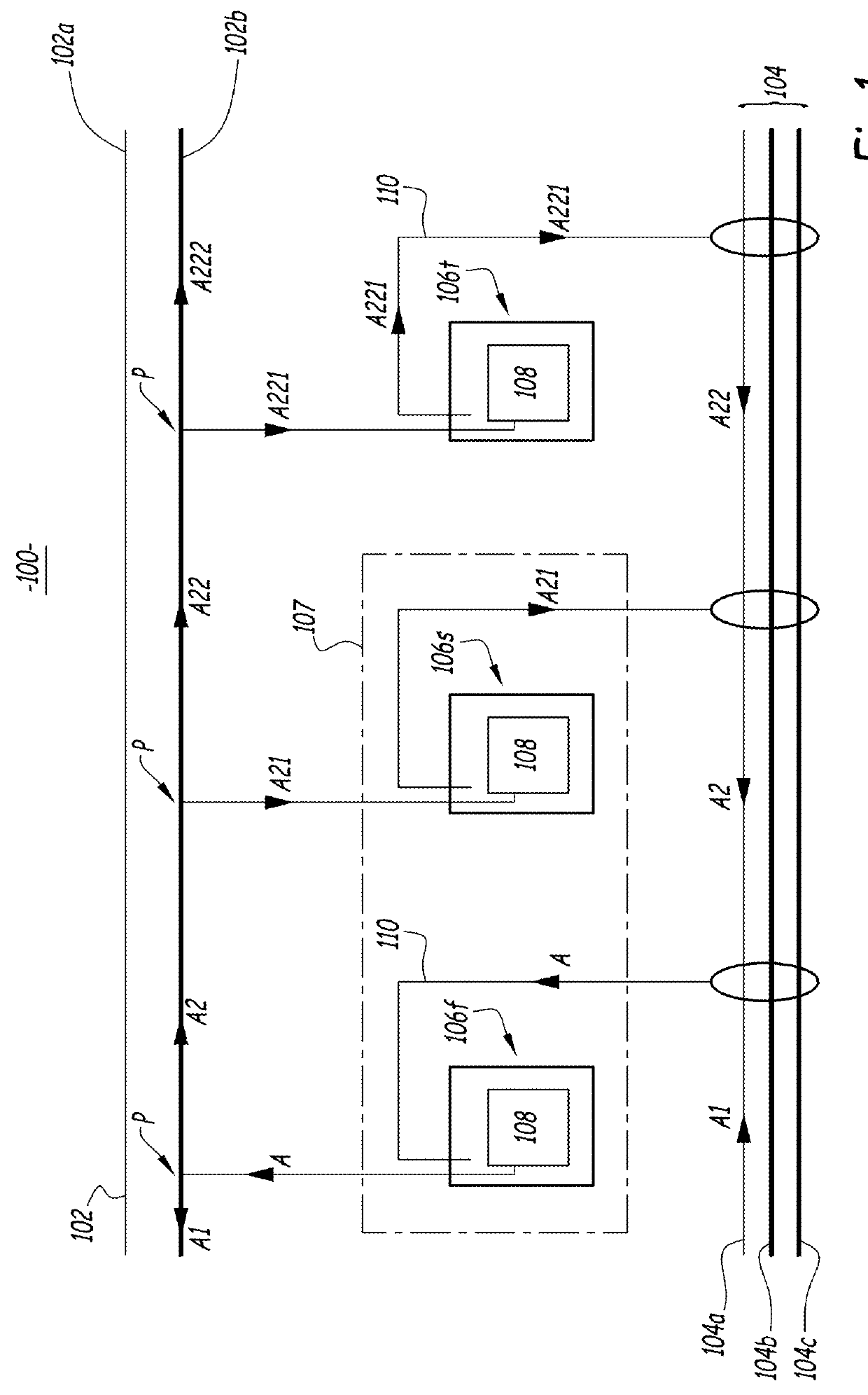
[0011]FIG. 1 illustrates a railroad track communication network 100 in accordance with one embodiment of the present invention. The communication network 100 includes a railroad track 102, a power line bundle 104 and three wayside control devices 106f, 106s and 106t. At least two of the three wayside control devices together form a communication system 107.

[0012]The railroad track 102 is made of two individual running rails 102a and 102b. Trains travel from one station to the other on railroad track 102.

[0013]The power line bundle 104 runs alongside the railroad track 102. It provides electrical power (preferably AC power) to wayside equipment located along the railroad track 102. The power line bundle 104 originates at a power substation (not shown). The bundle 104 has three power lines 104a, 104b and 104c. Line 104a corresponds to the hot line, line 104b to the neutral line, and line 104c to the ground line.

[0014]The three wayside control devices 106f, 106s and 106t are of the sam...


PUM


Abstract

A wayside communication system for transmitting coded current signals through running rails of a railroad track between wayside control devices. A power line common to the wayside control devices is used as the return path for the current signals. The system features train and broken rail detection. The system allows sending signals long distances since rail to rail current leakage is no longer an issue.

Description

BACKGROUND OF THE INVENTION[0001]The present invention relates generally to electric communication between wayside installations next to a railway track by sending a signal through the running rails of the railway track.[0002]U.S. Pat. No. 4,619,425 discloses an example of such electric communication. A solid state code transmitter and receiver device is located at each end of a railroad track section to alternatively transmit data codes through the rails to be received by the other end receiver element. One rail serves as the signal line while the other rail serves as the return path.[0003]One of the main problems with this type of communication is that signals cannot be sent over long distances. Indeed, in case of poor weather or rail or ballast conditions, rail to rail current leakage as well as current leakage to earth will degrade a signal significantly over long distances.BRIEF SUMMARY OF THE INVENTION[0004]In one embodiment, a communication system is provided for transmitting...

Claims


Application Information

Patent Timeline
Patent Type & Authority Applications(United States)
IPC IPC(8): B61L7/06B61L5/06H04B3/54
CPCB61L7/06H04B3/542B61L5/06B61L1/188B61L23/044B61L27/70
Inventor NAGRODSKY, NICHOLASLAWSON, RICHARDFRIES, JEFFREYHOUNSCHELL, JOHNKISS, JAMES
Owner ALSTOM TRANSPORT TECH SAS
Why Eureka
Try Eureka