Pulsed radar level gauge with single oscillator

a level gauge and radar technology, applied in the direction of pulse automatic control, liquid/fluent solid measurement, reradiation, etc., can solve the problem of components susceptible to drift between the two frequencies, and achieve the effect of improving the frequency generation

Active Publication Date: 2018-04-05
ROSEMOUNT TANK RADAR
View PDF0 Cites 5 Cited by
  • Summary
  • Abstract
  • Description
  • Claims
  • Application Information

AI Technical Summary

Benefits of technology

[0010]It is an object of the present invention to provide a pulsed radar

Problems solved by technology

However, this solution requires components which are susceptible to dr

Method used


Image

  • Pulsed radar level gauge with single oscillator
  • Pulsed radar level gauge with single oscillator
  • Pulsed radar level gauge with single oscillator

Examples


Embodiment Construction

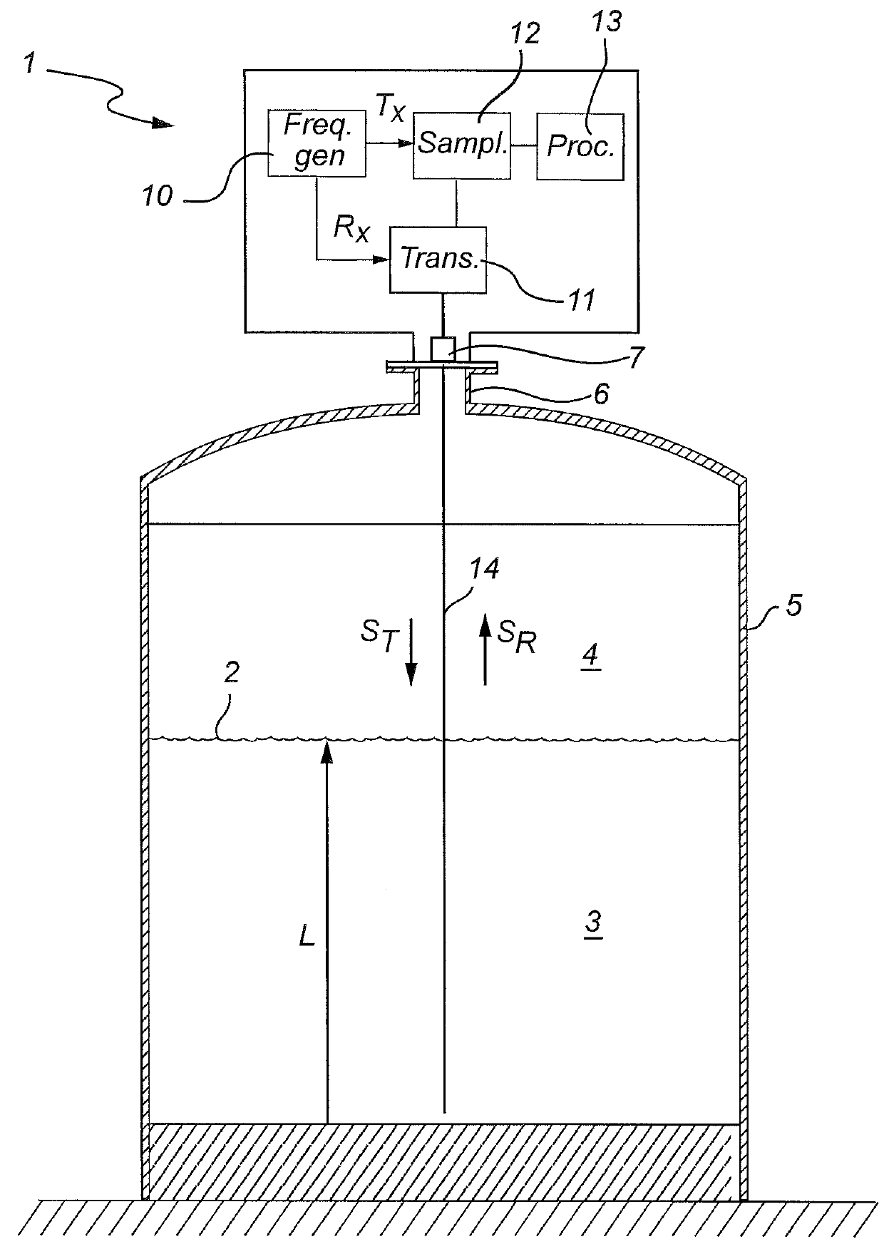
[0026]FIG. 1 shows schematically a pulsed radar level gauge (RLG) 1 arranged to measure a distance to an interface 2 between two (or more) materials 3, 4 in the tank 5. Typically, the first material 3 is a product stored in the tank, e.g. a liquid such as gasoline, while the second material 4 is air or some other atmosphere. In that case, the RLG will enable detection of the distance to the surface 2 of the content 3 in the tank, and from this determine the filling level L.

[0027]The tank 5 is provided with a fastening structure 6 securing the RLG 1 in a measuring position fixed relative the bottom of the tank 5. The RLG 1 includes a feed through structure 7, allowing transmission of signals into and out of the tank. The feed through structure 7 may be arranged to provide process seal, capable of withstanding temperature, pressure, and any chemicals contained in the tank.

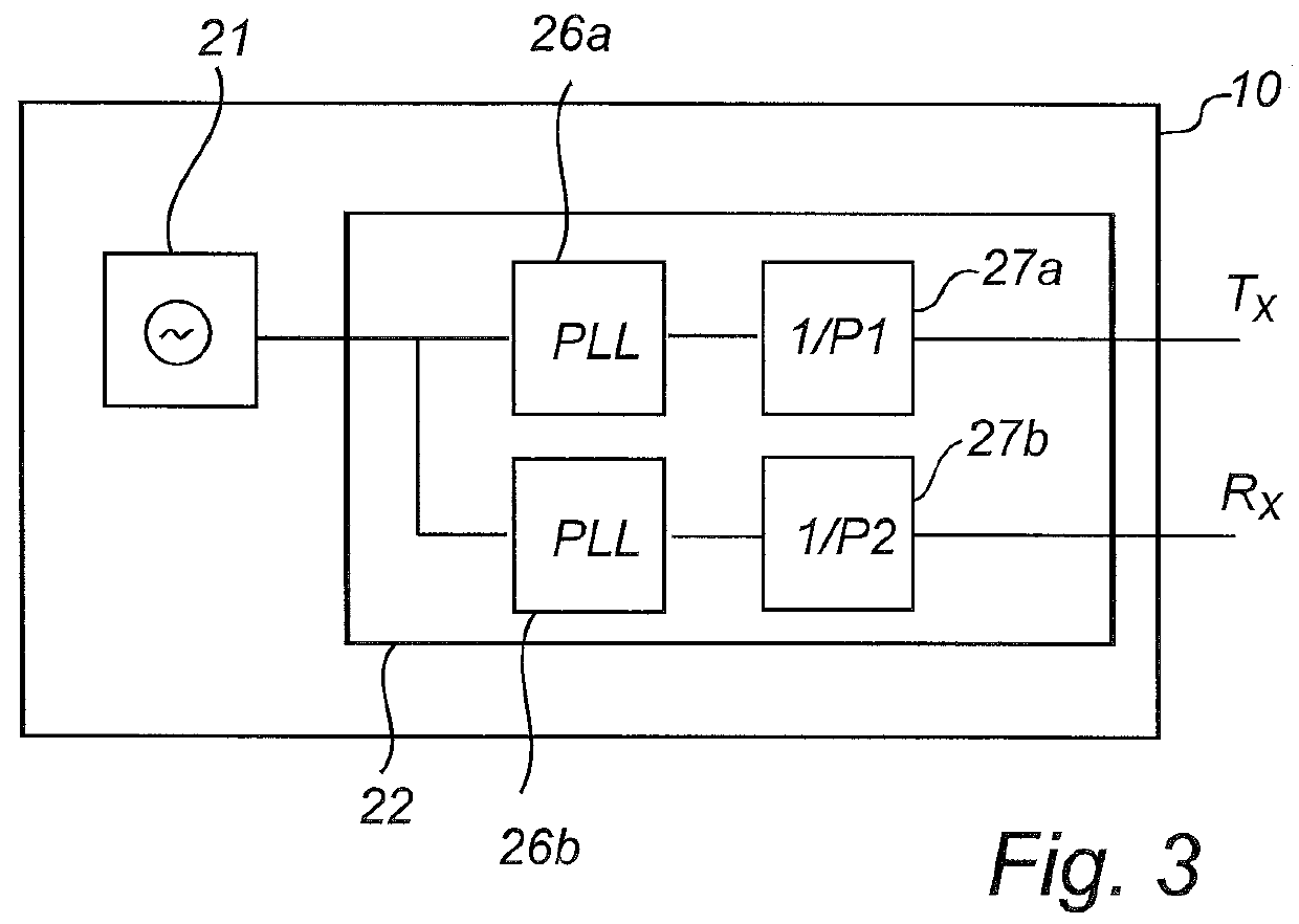
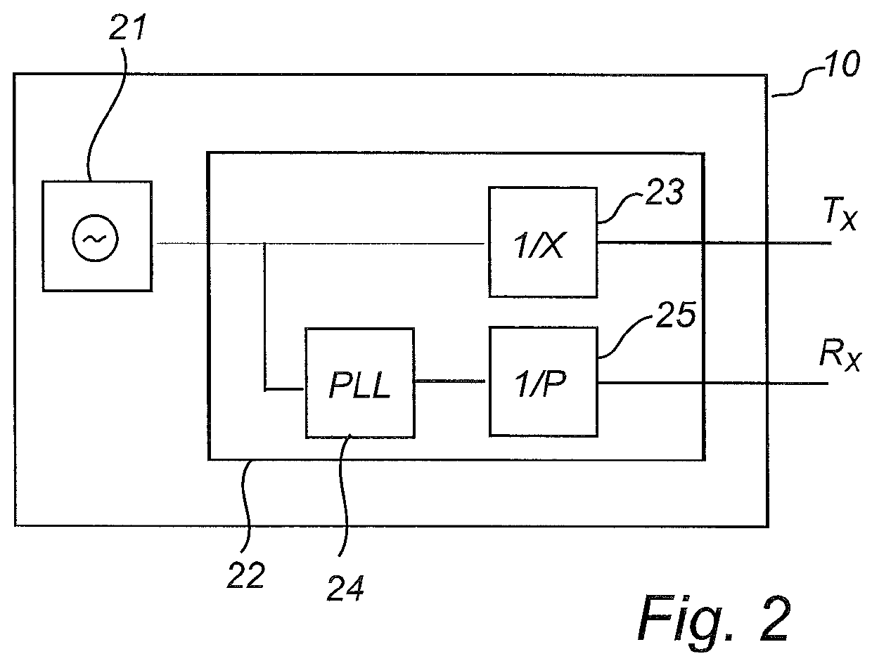
[0028]The RLG 1 comprises a frequency generator 10 for generating a Tx frequency signal connected to a transceiver...


PUM


Abstract

A pulsed radar level gauge for determining the filling level of a product contained in a tank, comprising a frequency generator for generating a Tx frequency signal and a Rx frequency signal. The frequency generator includes one single oscillating crystal for providing an oscillator frequency fosc and frequency modifying circuitry. The frequency modifying circuitry comprises a path including a PLL configured to receive said oscillator frequency fosc as input frequency and deliver a regulated output frequency being equal to the oscillator frequency fosc multiplied M/N, and a frequency divider connected to receive the regulated output frequency and deliver an output frequency equal to the regulated output frequency divided by an integer factor P.
A PLL combined with an integer frequency divider is used to generate at least one of the Tx and Rx frequencies based on an oscillator frequency provided by one single oscillator.

Description

FIELD OF THE INVENTION[0001]The present invention relates to a pulsed level gauge system with a single oscillator.TECHNICAL BACKGROUND[0002]Radar level gauge (RLG) systems are in wide use for determining the filling level of a product contained in a tank. Radar level gauging is generally performed either by means of non-contact measurement, whereby electromagnetic signals are radiated towards the product contained in the tank, or by means of contact measurement, often referred to as guided wave radar (GWR), whereby electromagnetic signals are guided towards and into the product by a probe acting as a waveguide. The probe is generally arranged to extend vertically from the top towards the bottom of the tank.[0003]The transmitted electromagnetic signals are reflected at the surface of the product, and the reflected signals are received by a receiver or transceiver comprised in the radar level gauge. Based on the transmitted and reflected signals, the distance to the surface of the pro...

Claims


Application Information

Patent Timeline
IPC IPC(8): G01F23/284H03L7/23G01S7/282
CPCG01F23/284G01S7/282H03L7/23G01S7/28G01S13/88H03L7/18
Inventor ERIKSSON, MIKAEL
Owner ROSEMOUNT TANK RADAR
Why Eureka
Try Eureka