Eureka AIR delivers breakthrough ideas for toughest innovation challenges, trusted by R&D personnel around the world.

Image forming apparatus

Active Publication Date: 2018-04-05
CANON KK
View PDF5 Cites 13 Cited by
  • Summary
  • Abstract
  • Description
  • Claims
  • Application Information

AI Technical Summary

Benefits of technology

The present invention is an image forming apparatus that includes a photosensitive drum and an LED print head. The apparatus includes a door that can be opened and closed for maintenance. The LED print head is supported by a support portion that moves in conjunction with the opening and closing movements of the door. A guide portion is formed on the door to guide a cleaning member to the LED print head. The guide portion has a first inclined surface that holds the cleaning member in continuous contact with the LED print head when the door is open and the LED print head is positioned at the second position. This configuration allows for easy cleaning of the LED print head without interrupting the printing process.

Problems solved by technology

Therefore, toner is liable to adhere to the LED print head.
Therefore, occurrence of image defects such as density unevenness is concerned.
With regard to the cleaning member of the image forming apparatus disclosed in Japanese Patent Application Laid-Open No. 2010-230954, even when a member which is less liable to damage the surface of the photosensitive drum is used for the protection member, the surface of the photosensitive member may be damaged by rubbing.
In particular, when an adhering matter is present on the protection member, the adhering matter may damage the surface of the photosensitive drum.
For such an image forming apparatus, it is not practical to clean the LED print head with use of the cleaning member disclosed in Japanese Patent Application Laid-Open No. 2010-230954.

Method used


Image

  • Image forming apparatus
  • Image forming apparatus
  • Image forming apparatus

Examples


first embodiment

[0029]Now, description is made of an embodiment of the present invention along the drawings.

[0030][Configuration of Image Forming Apparatus]

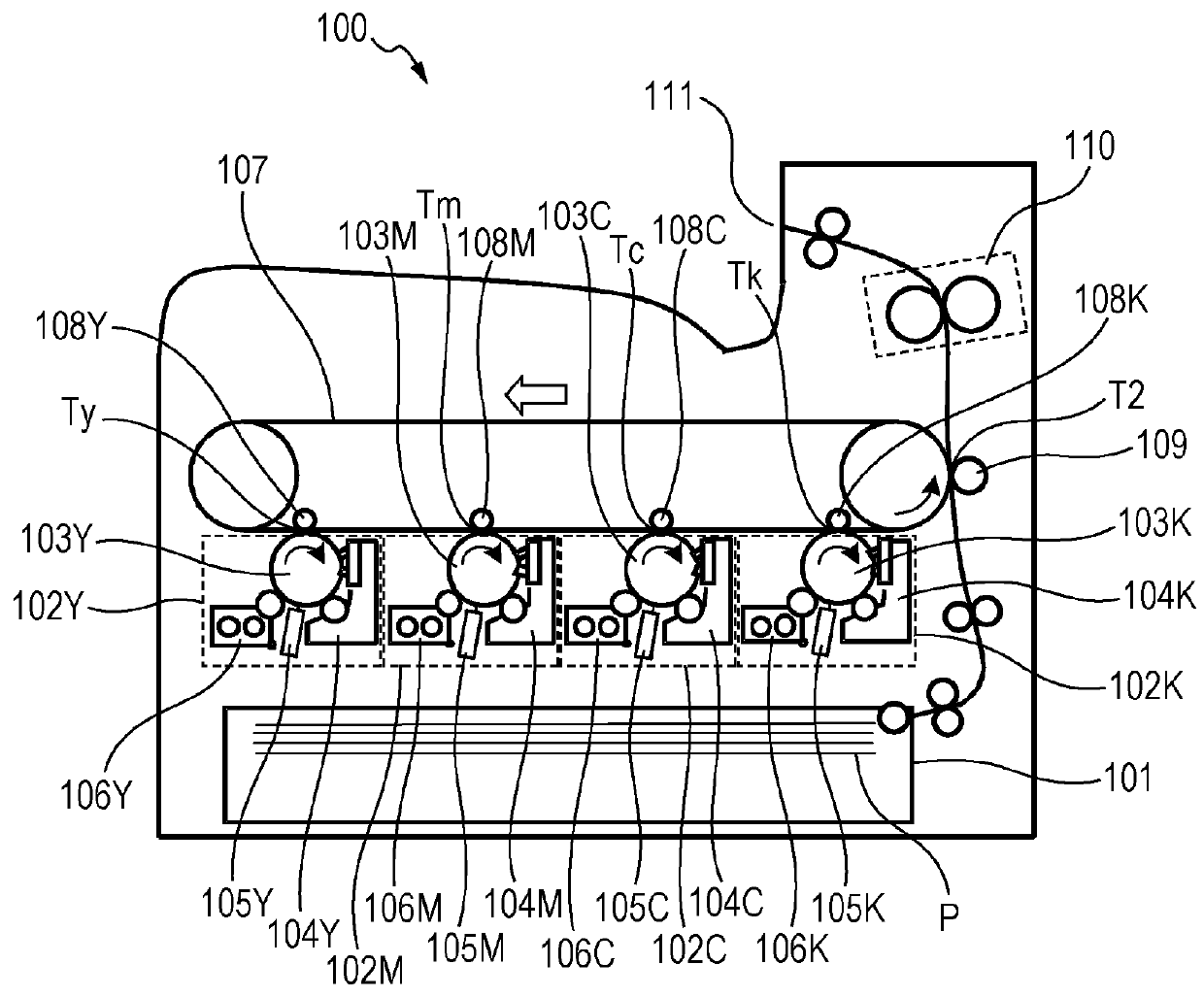
[0031]FIG. 1 is a schematic sectional view of an image forming apparatus 100 of an electrophotographic type according to a first embodiment of the present invention. The image forming apparatus 100 is an image forming apparatus of a so-called tandem type, which includes photosensitive members for respective colors including yellow (Y), magenta (M), cyan (C), and black (K) and is configured to superimpose images of the respective colors on an intermediate transfer member and collectively transfer the images onto a sheet. The image forming apparatus 100 includes a sheet-feeding unit 101, image forming portions 102Y, 102M, 102C, and 102K, an intermediate transfer belt 107, and a fixing device 110. In the following, reference symbols Y, M, C, and K denoting colors of toner are omitted unless otherwise needed.

[0032]The sheet-feeding unit 101 is confi...

second embodiment

[0058]In the first embodiment, the shape of the guide portion 250a provided to the inner door 250 is set so as to allow the cleaning member 10 to be inserted obliquely from the upper side to the lower side. In the second embodiment, description is made of a shape of the guide portion which enables the LED print head 105 to be reliably cleaned by only causing the cleaning member 10 to reciprocate in the horizontal direction without need of being aware of the angle of insertion of the cleaning member 10.

[0059][Shape of Guide Portion]

[0060]FIG. 11A is a perspective view for illustrating a shape of a guide portion 250b provided to the inner door 250 of the second embodiment. FIG. 11B is a sectional view of the inner door 250 including the guide portion 250b as viewed from the left side in FIG. 1. In FIG. 11A, FIG. 11B, and FIG. 11C, the links 252 are omitted. As illustrated in FIG. 11A, similarly to the guide portion 250a of the first embodiment, the guide portion 250b is provided at a ...


PUM


Abstract

An image forming apparatus includes: an LED print head exposing a photosensitive drum with light; a door arranged on one end side of the LED print head; a support portion for the LED print head operating in conjunction with opening and closing movements of the door, positioning the LED print head at a first position for exposing the photosensitive drum when the door is closed, and positioning the LED print head at a second position more apart from the photosensitive drum than the first position when the door is open; and a guide portion formed on the door and guiding a cleaning member to the LED print head, the guide portion having a first inclined surface which is lowered toward the LED print head so that the cleaning member is continuously held in contact with the LED print head under a state in which the door is open.

Description

BACKGROUND OF THE INVENTIONField of the Invention[0001]The present invention relates to an image forming apparatus of an electrophotographic type, such as a copying machine, a printer, or a facsimile, to which a light-emitting element array is mounted.Description of the Related Art[0002]An image forming apparatus of an electrophotographic type such as a printer or a digital copying machine may include an LED print head serving as a light source configured to expose a photosensitive drum with light. The LED print head is an exposure light source including a predetermined number of LEDs arrayed in a direction intersecting a rotation direction of the photosensitive drum. That is, the predetermined number of LEDs are arranged at different positions in the direction intersecting the rotation direction of the photosensitive drum, and each LED forms one pixel in this direction. The LED print head occupies a smaller volume in the apparatus as compared to a laser scanner unit (hereinafter re...

Claims


Application Information

Patent Timeline
IPC IPC(8): B41J2/385
CPCG03G21/169G03G15/04054G03G21/1633G03G21/1666G03G21/00G03G15/326G03G2215/0409G03G2221/1654G03G2221/169G03G15/052G03G21/007H04N1/028H04N2201/0093H04N2201/0082
Inventor IWAI, HITOSHIHOSOI, SHINICHIROISHIDATE, TAKEHIRO
Owner CANON KK
Why Eureka
Eureka Blog
Learn More