Unlock instant, AI-driven research and patent intelligence for your innovation.

Brightness compensation method, system and display panel in demura system

a brightness compensation and demura system technology, applied in the field of display, can solve the problems of serious brightness decay, and achieve the effect of reducing the influence of reducing the influence of view angle, and reducing the offset of brightness decay

Active Publication Date: 2018-04-05
SHENZHEN CHINA STAR OPTOELECTRONICS TECH CO LTD
View PDF5 Cites 3 Cited by
  • Summary
  • Abstract
  • Description
  • Claims
  • Application Information

AI Technical Summary

Benefits of technology

The present invention provides a brightness compensation method in a Demura system that reduces the impact of angle and cost on brightness decay. This method uses a f(θ) function to divide the brightness value, resulting in a better compensation outcome. The technical effect is a reduction in brightness decay offset, resulting in improved brightness performance.

Problems solved by technology

The larger the size of the liquid crystal screen is, the more serious the brightness decay becomes.

Method used


Image

  • Brightness compensation method, system and display panel in demura system
  • Brightness compensation method, system and display panel in demura system
  • Brightness compensation method, system and display panel in demura system

Examples


Embodiment Construction

[0044]Embodiments of the present invention are described in detail with the technical matters, structural features, achieved objects, and effects with reference to the accompanying drawings as follows. It is clear that the described embodiments are part of embodiments of the present invention, but not all embodiments. Based on the embodiments of the present invention, all other embodiments to those of ordinary skill in the premise of no creative efforts obtained, should be considered within the scope of protection of the present invention.

[0045]Please refer to FIG. 2. FIG. 2 shows a brightness compensation method in a Demura system in the first preferred embodiment of the present invention. The method is accomplished with the display penal or the display device. As shown in FIG. 2, the method comprises steps of:

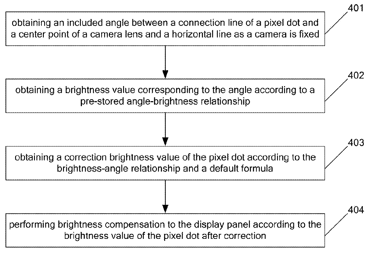
[0046]step S201, obtaining an included angle θ between a connection line of a pixel dot and a center point of a camera lens and a horizontal line as a camera is fixed;

[0047]T...


PUM


Abstract

The present invention provides a brightness compensation method, a system and a display panel in a Demura system. The method comprises obtaining an included angle θ between a connection line of a pixel dot and a center point of a camera lens and a horizontal line as a camera is fixed; obtaining a brightness value f(θ) corresponding to the θ according to a pre-stored angle-brightness relationship; obtaining a correction brightness value of the pixel dot according to a calculation of the f(θ) and a default formula, and performing brightness compensation to the display panel according to the brightness value of the pixel dot after correction. The technical solution provided by the present invention can reduce the influence of the view angle to the brightness and the influence of cos4 θ to the brightness, and thus, it possesses the benefit of the brightness decay offset reduction.

Description

CROSS REFERENCE[0001]This application claims the priority of Chinese Patent Application No. 201510961480.2, entitled “Brightness compensation method, system and display panel in Demura system”, filed on Dec. 21, 2015, the disclosure of which is incorporated herein by reference in its entirety.FIELD OF THE INVENTION[0002]The present invention relates to a display field, and more particularly to a brightness compensation method, a system and a display panel in a Demura system.BACKGROUND OF THE INVENTION[0003]The panel is also so called the LCD (Liquid Crystal Display), which is a common electronic display device at present. The present Demura system of the LCD performs compensation according to the brightness.[0004]In the solution of realizing prior art, the following technical issue is found:[0005]In prior art, the Demura system generally performs compensation according to the brightness of the camera. However, in prior art, there will be offset of the brightness due to the angle as ...

Claims


Application Information

Patent Timeline
IPC IPC(8): G09G3/36H05B37/02G02F1/13G09G3/3233H05B44/00
CPCG09G3/36H05B37/02G02F1/13G09G3/3233G09G3/342G09G3/006G09G2320/0285G09G2320/0693G09G2360/145G09G2320/068
Inventor KUO, PING-SHENGZHU, LIWEI
Owner SHENZHEN CHINA STAR OPTOELECTRONICS TECH CO LTD
Features
  • R&D
  • Intellectual Property
  • Life Sciences
  • Materials
  • Tech Scout
  • Unparalleled Data Quality
  • Higher Quality Content
  • 60% Fewer Hallucinations
Learn More