Massaging device

a technology of massaging device and massaging body, which is applied in the field of massaging device, can solve the problems of not providing different massaging force or effect to users, and achieve the effect of improving and simplifying the structure or configuration, making or manufacturing or facilitating and fasting

Inactive Publication Date: 2018-04-12
CHEN PAUL
View PDF13 Cites 1 Cited by
  • Summary
  • Abstract
  • Description
  • Claims
  • Application Information

AI Technical Summary

Benefits of technology

[0008]The primary objective of the present invention is to provide a massaging device including an improved and simplified structure or configuration that may be easily and quickly made or manufactured or assembled by the workers.

Problems solved by technology

However, the outer layer includes a smooth outer peripheral structure or contour that may not be frictionally contacted or engaged with the users such that the users may not be massaged with the typical massaging devices.
However, the projections or protrusions extended outwardly from the planar base member, but may not be adjusted relative to the planar base member, and thus may not provide different massaging forces or effects to the users.

Method used


Image

  • Massaging device
  • Massaging device
  • Massaging device

Examples


Embodiment Construction

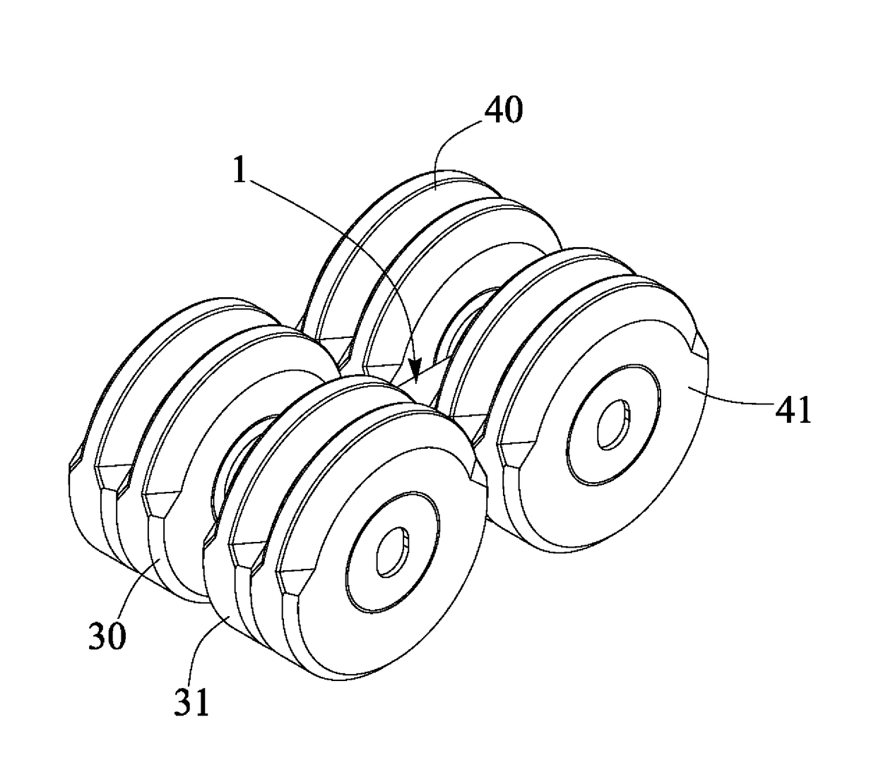
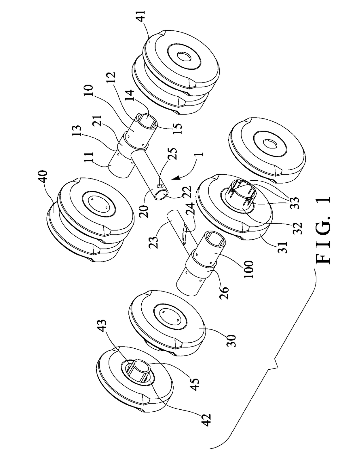
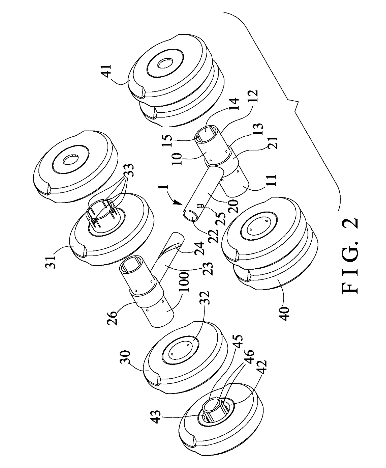
[0024]Referring to the drawings, and initially to FIGS. 1-6, a massaging device in accordance with the present invention comprises a handle device 1 including a first shank or shaft 10 having two end portions 11, 12, such as one or first end portion 11, another or second end portion 12 or the like, and a middle or intermediate portion 13, and including a handlebar 20 having one or first end portion 21 attached or mounted or secured to the middle portion 13 of the shaft 10 and perpendicular to the shaft 10 for forming or defining a substantially T-shaped structure or configuration, the shaft 10 includes a bore or inner compartment or chamber 14 formed therein (FIGS. 1-2, 5), and including one or more (such as four) elongated or longitudinal grooves or channels 15 formed therein and communicating with the chamber 14 of the shaft 10. The handlebar 20 includes a bore or inner chamber or compartment 22 formed therein.

[0025]The handle device 1 further includes an extension or shank 23 mov...


PUM


Abstract

A massaging device includes a shaft having two end portions, a handlebar attached to the shaft and perpendicular to the shaft, and a massaging member attached to the shaft. The massaging member is attached to either of the end portions of the shaft. The handlebar includes one end portion attached to the middle portion of the shaft and perpendicular to the shaft for forming a T-shaped structure. The massaging member is attached to the shaft with a fastener. A massaging element is attached to the shaft and includes a barrel having a space for engaging with the shaft. The massaging member includes a cylindrical ember having one or more spring biased latches engaged with the massaging element.

Description

BACKGROUND OF THE INVENTION1. Field of the Invention[0001]The present invention relates to a massaging device, and more particularly to a massaging device including an improved and simplified structure or configuration that may be easily and quickly made or manufactured or assembled by the workers and including an adjustable structure or configuration for adjusting the arrangement of the massaging members and for adjusting the massaging effects to the users.2. Description of the Prior Art[0002]Typical massaging devices comprise a relatively harder or stronger inner housing, and a relatively softer or resilient outer layer for selectively contacting or engaging with the users and for massaging purposes.[0003]For example, U.S. Pat. No. 4,807,603 to Yasui discloses one of the typical massaging devices also comprising a relatively harder or stronger inner housing having a cylindrical shape, and a relatively softer or resilient outer layer for selectively contacting or engaging with the ...

Claims


Application Information

Patent Timeline
Patent Type & Authority Applications(United States)
IPC IPC(8): A61H1/00A61H15/00
CPCA61H15/0092A61H1/008A61H2015/0035A61H2201/0107A61H2201/1685
Inventor CHEN, PAUL
Owner CHEN PAUL
Why Eureka
Try Eureka