Container assembly and closure with predetermined humidity and related method

a technology of predetermined humidity and container, applied in the direction of liquid handling, packaging, cap, etc., can solve the problems of loose packets being intentionally or mistakenly discarded, requiring special materials, and confusion among consumers as to whether the packet is something other than a humidity control devi

Active Publication Date: 2018-04-12
DRUG PLASTIC & GLASS +1
View PDF4 Cites 7 Cited by
  • Summary
  • Abstract
  • Description
  • Claims
  • Application Information

AI Technical Summary

Benefits of technology

[0027]FIG. 14 is a schematic view of a process for manufacturing a humidity control device that may be utilized with any of the preferred embodiments of the container assembly disclosed herein.

Problems solved by technology

However, this method of providing the humidity control feature through pouches that are loose in the product package creates inconvenience, potential contamination and perception disadvantages, such that manufacturers or consumers refuse to, or are prevented from, using this approach.
For example, consumer confusion may arise as to whether the packet is something other than a humidity control device.
In some cases, loose packets may be intentionally or mistakenly discarded by consumers when opening and closing the product packaging, particularly with repeated opening and closing of the packaging over time and opening or closing by consumers who are not familiar with the purpose of the pouch.
Such approaches may also require specialized materials.
Such intermingling and direct contact between the pouches and products are generally undesirable and consumers prefer not to have the pouches intermingled with the product such that the pouches fall out of the container when the consumer is dispensing products for use and the pouches come into direct contact with the stored products during storage and transport.
There is no generally known system or method for adding and removing moisture to the contents of the container during typical use and appropriately isolating the RH control material.

Method used


Image

  • Container assembly and closure with predetermined humidity and related method
  • Container assembly and closure with predetermined humidity and related method
  • Container assembly and closure with predetermined humidity and related method

Examples


Embodiment Construction

[0028]Certain terminology is used in the following description for convenience only and is not limiting. Unless specifically set forth herein, the terms “a”, “an” and “the” are not limited to one element but instead should be read as meaning “at least one”. The words “right”, “left”, “lower” and “upper” designate directions in the drawings to which reference is made. The words “inwardly” or “distally” and “outwardly” or “proximally” refer to directions toward and away from, respectively, the container assembly, the container, the cap and related parts thereof. The words, “anterior”, “posterior”, “superior,”“inferior”, “lateral” and related words and / or phrases designate preferred positions, directions and / or orientations to which reference is made and are not meant to be limiting. The terminology includes the above-listed words, derivatives thereof and words of similar import.

[0029]It should also be understood that the terms “about,”“approximately,”“generally,”“substantially” and li...


PUM


Abstract

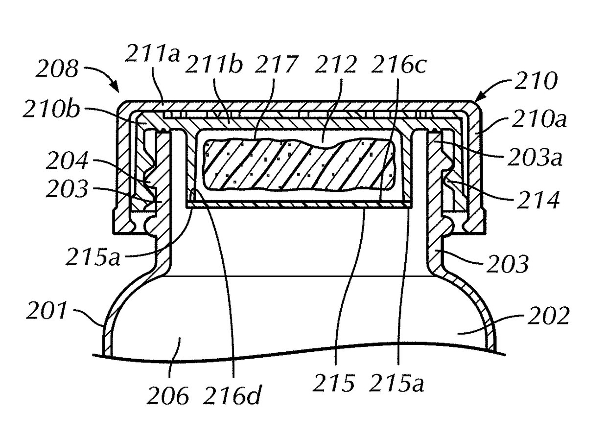
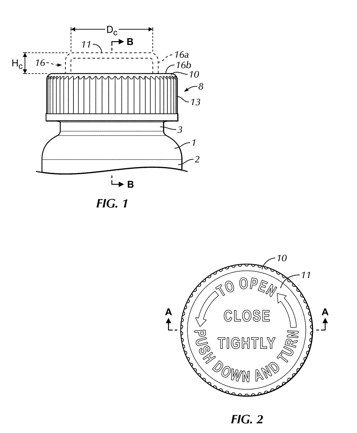
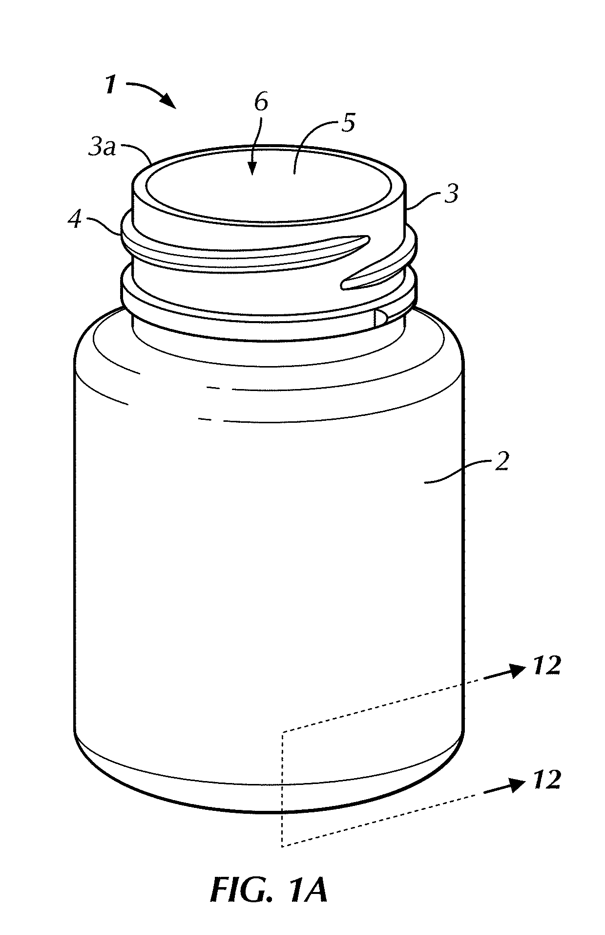
A container assembly configured to maintain a predetermined humidity for storing a product therein. The container assembly includes a container having a body with a body wall and a mouth opening into a storage cavity and a cap having a top wall. The cap is selectively mountable over the mouth of the container to substantially enclose the storage cavity in a mounted configuration. A sidewall extends substantially perpendicularly from one of the body wall and the top wall. The sidewall defines an opening and a compartment and has an opening edge adjacent the opening. A moisture control material is positioned within the compartment. A sealing membrane has a peripheral portion. The peripheral portion is secured to the sidewall proximate the opening edge. The sealing membrane is configured to allow moisture flow therethrough to maintain the predetermined humidity in the storage cavity.

Description

CROSS-REFERENCE TO RELATED APPLICATIONS[0001]The present application claims the benefit of U.S. Provisional Patent Application No. 62 / 422,317, filed Nov. 15, 2016 and titled, “Container Assembly with Predetermined Humidity and Related Method,” the entire contents of which is incorporated herein by reference in its entirety. The present application also claims the benefit of U.S. Provisional Patent Application No. 62 / 407,269 (“269-APP”), filed on Oct. 12, 2016 and titled, “Device for Controlling Headspace Humidity and Methods for Making the Same” to the extent that subject matter from the 269-APP is expressly repeated herein.BACKGROUND OF THE INVENTION[0002]There is a need to keep pharmaceutical, health care and other products at a constant and regulated moisture level when they are stored in a container assembly. The packaging industry has been challenged to provide a package that is clean, a barrier to moisture vapor, child resistant and now having a means to keep the product fresh...

Claims


Application Information

Patent Timeline
Patent Type & Authority Applications(United States)
IPC IPC(8): B65D51/30B65D41/20B65D50/04
CPCB65D51/30B65D41/20B65D50/04B65D81/266B65D43/162B65D50/041B65D2543/00092B65D2543/00296B65D2543/00518B65D2543/0062B65D2543/00685B65D2543/0074B65D2543/00796B65D50/043B65D51/18B65D81/22B65D81/264B65D2251/0015B65D2251/009
Inventor BIESECKER LONGACRE, LISSABIESECKER, II, FREDERICK N.CAMOMILE, DOUGLAS S.CLEEVELY, BRUCE T.WARMKESSEL, ALEX M.ESSE, ROBERTBOHRER, TIMOTHY H.RICE, BRIANMOLL, KYLE A.WELLER, ERIC
Owner DRUG PLASTIC & GLASS
Why Eureka
Try Eureka