System and methods for providing and using a knee range of motion device

knee joint technology, applied in the field of systems and methods for providing a knee range of motion device, can solve the problems of scar tissue formation, limited knee range of motion, and stiff knee, and achieve the effect of improving the quality of life and reducing the risk of injury

Active Publication Date: 2018-04-19
DYNATRONICS CORP
View PDF0 Cites 10 Cited by
  • Summary
  • Abstract
  • Description
  • Claims
  • Application Information

AI Technical Summary

Benefits of technology

[0006]The present invention relates to systems and methods for providing a knee range of motion device. In some implementations, the described device includes a knee arm that is configured to pivot through a range of motion and a drive mechanism that is configured to force the knee arm through the range of motion. In some cases, the drive mechanism includes a first hard stop that prevents the knee arm from extending past a first set point, and the drive mechanism further includes a second hard stop that prevents the knee arm from being retracted past a second set point. In some cases, the device is further configured to be programmed to electronically limit and / or adjust the knee arm's range of motion. In some cases, the device further comprises a remote stop that is configured to allow a user to immediately stop the knee arm from moving through the range of motion.

Problems solved by technology

Often times, after a knee or leg has been operated on, damaged, or otherwise injured, the knee can become stiff and the knee's range of motion can become limited.
In some cases, if such a knee is not rehabilitated, scar tissue can form and the knee's range of motion can be permanently limited.
In some instances, where the knee's range of motion is limited, not only can use of the knee be relatively painful, but the knee's limitations can result in a loss of mobility and in future back, hip, knee, and leg pain.
While many such devices may be useful at helping to increase a knee's range of motion, such devices are not necessarily without their shortcomings.
Indeed, some conventional physical therapy devices are relatively dangerous to use—exposing their users to a significantly high risk of injury.
Additionally, some conventional physical therapy devices can be complicated to use and difficult to tailor to a specific user's needs and desires.
Thus, while techniques currently exist that are used to rehabilitate knees, challenges still exist, including those discussed above.

Method used


Image

  • System and methods for providing and using a knee range of motion device
  • System and methods for providing and using a knee range of motion device
  • System and methods for providing and using a knee range of motion device

Examples


Embodiment Construction

[0027]Reference throughout this specification to “one embodiment,”“an embodiment,”“an implementation,” and similar language means that a particular feature, structure, or characteristic described in connection with the embodiment or implementation is included in at least one embodiment of the present invention. Thus, appearances of the phrases “in one embodiment,”“in an embodiment,”“in another embodiment,”“in some implementations,”“in some other embodiments,”“in some other implementations,” and similar language throughout this specification may, but do not necessarily, all refer to the same embodiment or implementation.

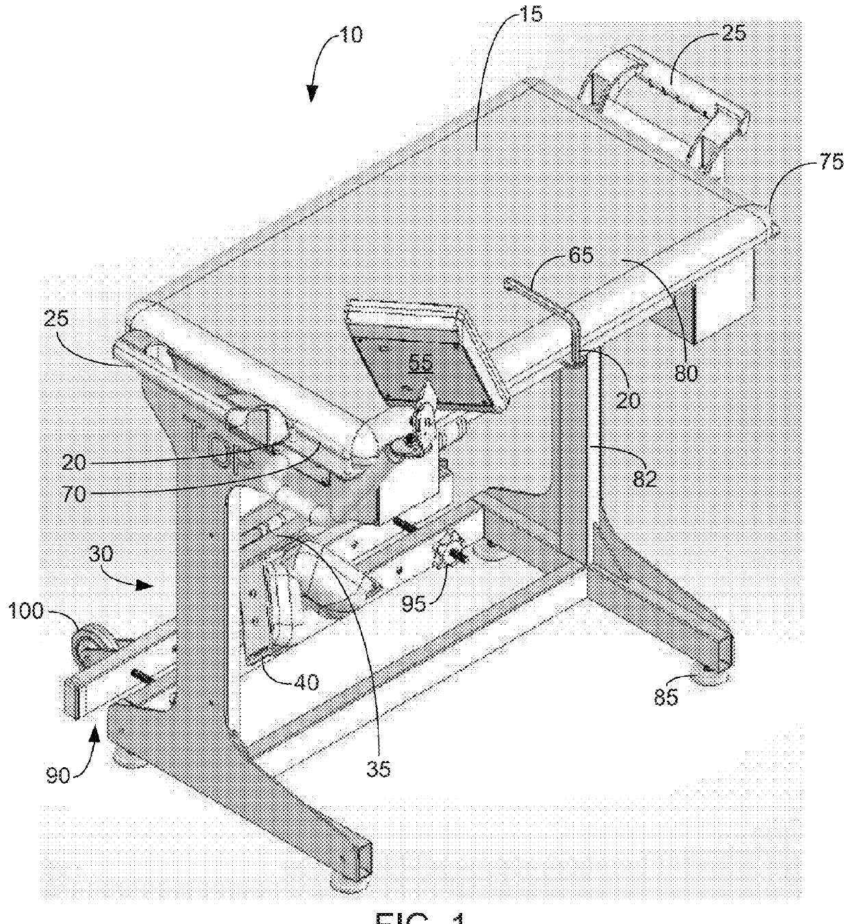
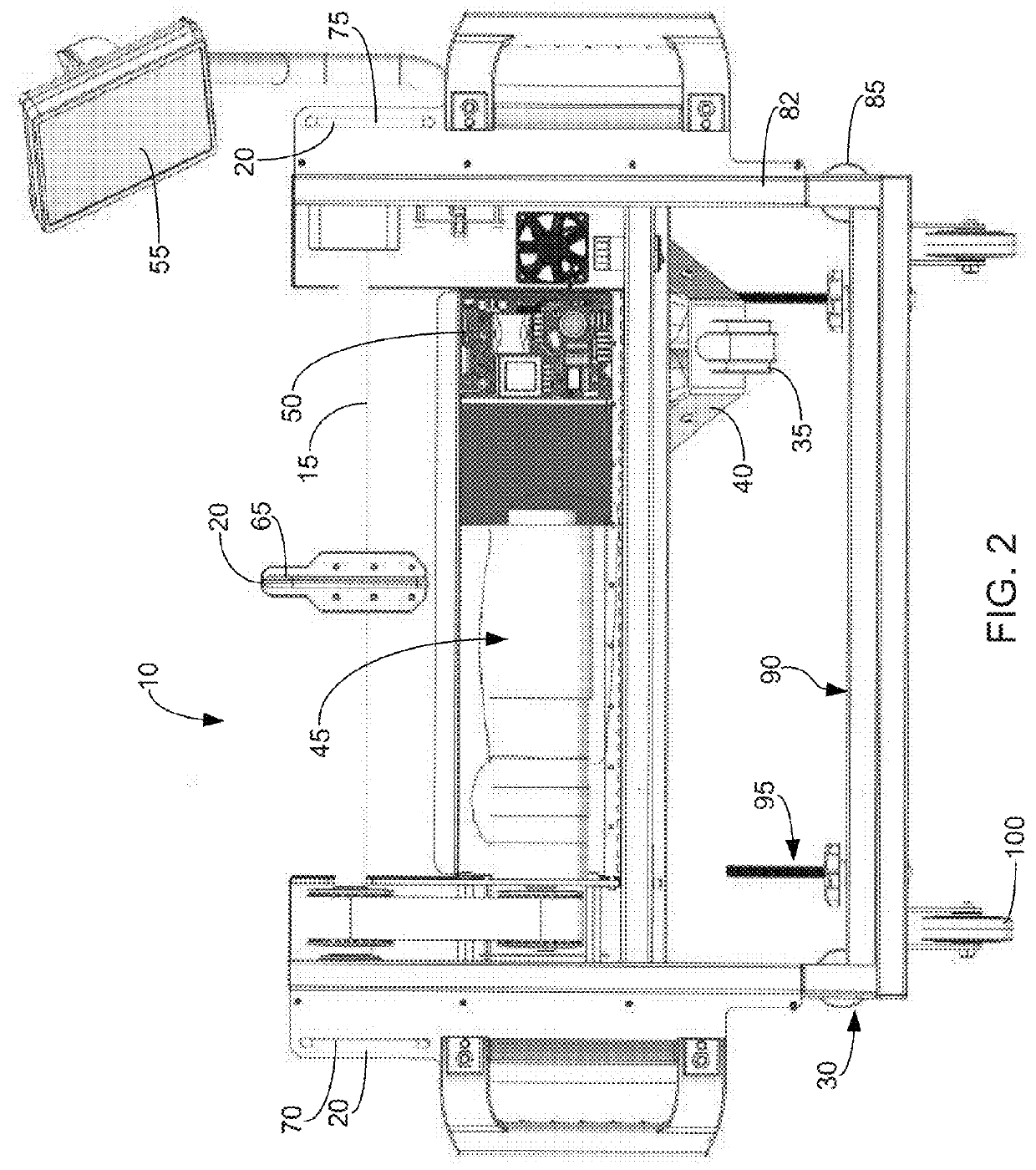
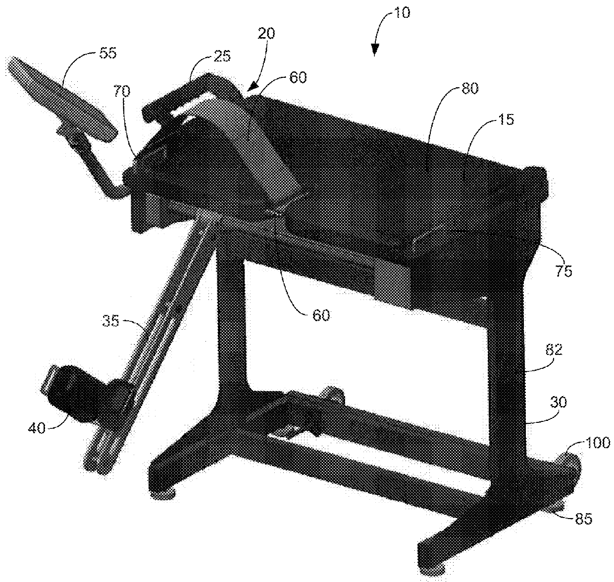
[0028]Furthermore, the described features, structures, or characteristics of the described systems and methods may be combined in any suitable manner in one or more embodiments. In the following description, numerous specific details are provided, such as examples of suitable support surfaces, support structures, knee arms, leg coupling mechanisms, drive mechanisms, u...


PUM


Abstract

The described knee rehabilitation device can include any suitable component. In some implementations, however, it includes a sitting surface that is configured to support a user; a knee arm that comprises a leg coupling mechanism, that is pivotally coupled to the rehabilitation device, and that is configured to pivot through a range of motion; and a drive mechanism that is configured to force the knee arm through the range of motion. In some cases, the drive mechanism includes a first hard stop that prevents the knee arm from extending past a first set point, and the drive mechanism further includes a second hard stop that prevents the knee arm from being retracted past a second set point. In some cases, the device is further configured to be programmed to electronically limit the knee arm's range of motion. Other implementations are discussed.

Description

CROSS-REFERENCE TO RELATED APPLICATION[0001]This non-provisional application claims priority to U.S. Provisional Patent Application Ser. No. 62 / 410,183 (Attorney Docket No. 7536.128), filed Oct. 19, 2016 and entitled “SYSTEMS AND METHODS FOR PROVIDING AND USING A KNEE RANGE OF MOTION DEVICE,” the entire disclosure of which is hereby incorporated by reference.BACKGROUND OF THE INVENTION1. Field of the Invention[0002]The present invention relates to systems and methods for providing a knee range of motion device. In some implementations, the described device includes a knee arm that is configured to pivot through a range of motion and a drive mechanism that is configured to force the knee arm through the range of motion. In some cases, the drive mechanism includes a first hard stop that prevents the knee arm from extending past a first set point, and the drive mechanism further includes a second hard stop that prevents the knee arm from being retracted past a second set point. In some...

Claims


Application Information

Patent Timeline
Patent Type & Authority Applications(United States)
IPC IPC(8): A61H1/02
CPCA61H1/024A61H1/0277A61H1/0244A61H1/0285A61H1/0288A61H1/0281A61H1/0266A61H2201/1215A61H2201/1642A61H2205/102A61H2201/1671A61H2201/5007A61H2201/5012A61H2201/5064A61H2201/1676A61H2201/501A61H2201/5066A61H2201/5069
Inventor SAMPSON, DOUGLASDYKE, JOHN WILLIAMMABEY, SCOTT RUSSELLSMALLEY, MOSIAH TROYSPENCER, CHRISTOPHER EDWIN
Owner DYNATRONICS CORP
Why Eureka
Try Eureka