
Latch for a Ball and Sleeve Plunger

a technology of sleeve and ball, which is applied in the direction of fluid removal, borehole/well accessories, construction, etc., can solve the problems of ball to be unseated, and the wall of the sleeve being susceptible to premature failure, so as to facilitate the removal of the retaining ring

Active Publication Date: 2018-04-26
FLOWCO PRODION SOLUTIONS
View PDF6 Cites 1 Cited by
  • Summary
  • Abstract
  • Description
  • Claims
  • Application Information

AI Technical Summary

Benefits of technology

This patent describes a mechanism for holding a ball and sleeve in place during an ascent and descent of a plunger in a well. The mechanism includes a groove in the inside of the sleeve and a retaining ring installed in the groove. The groove and retaining ring are designed to have a specific cross-section profile and to allow for expansion and contraction of the retaining ring as the plunger moves. The mechanism can be easily removed using a punch or a prying tool. Overall, this mechanism ensures the stability of the ball and sleeve during use of the plunger.

Problems solved by technology

The ascent is often not smooth, but subject to substantial jarring impacts that may cause the ball to become unseated if it is not latched in position against its seat.
This arrangement weakens the wall of the sleeve, making the sleeve susceptible to premature failure—i.e., well before the sleeve itself is worn out from many cycles of use—when it encounters the high impact force as it contacts the bumper at the end of its descent.

Method used


Image

  • Latch for a Ball and Sleeve Plunger
  • Latch for a Ball and Sleeve Plunger
  • Latch for a Ball and Sleeve Plunger

Examples


Embodiment Construction

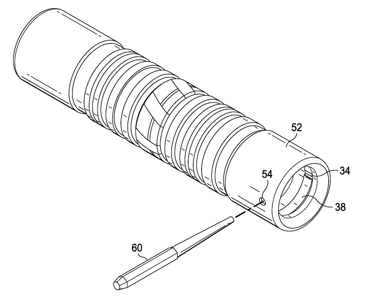
[0026]In an advance in the state of the art, an improved latching mechanism is described herein that extends the useful life of a two-piece ball and sleeve bypass plunger. The latching mechanism includes a single split retaining ring installed in a groove formed in the inside diameter of the sleeve portion of the bypass plunger. When the ball component is not in the plunger, the quiescent inside diameter of the retaining ring is slightly less than the diameter of the ball component. The groove is positioned relative to the spherical valve seat so the when the ball component of the valve is seated against the valve seat, the largest diameter portion of the ball is disposed just past the retaining ring, which expands slightly to allow the ball to pass through the ring and seat against the spherical valve seat. This is because the inside diameter of the retaining ring must be slightly smaller than the diameter of the ball to act as an effective latch mechanism. The cross section profil...


PUM


Abstract

An improved latch structure for a two piece ball and sleeve bypass plunger comprises a single retaining ring installed in a groove formed in the inside diameter of the sleeve portion of the bypass plunger. The cross section profiles of the groove and the associated retaining ring are smaller in the radial direction. The depth of the groove in the sleeve is substantially reduced to provide increased wall thickness and robustness of the sleeve along the diameter of the sleeve, thereby extending the useful life of the bypass plunger.

Description

CROSS REFERENCE TO RELATED APPLICATIONS[0001]This application claims priority to U.S. Provisional Patent Application Ser. No. 62 / 412,959 filed 26 Oct. 2016, by the same inventors and entitled IMPROVED LATCH FOR A BALL AND SLEEVE PLUNGER.BACKGROUND OF THE INVENTION1. Field of the Invention[0002]The present invention generally relates to bypass plungers for lifting fluids from an oil or gas well that has insufficient pressure to sustain production, and more particularly to an improved latch for a two-piece ball and sleeve bypass plunger.2. Background of the Invention and Description of the Prior Art[0003]Two piece ball and sleeve bypass plungers are simple devices well-known in the art. The hollow sleeve includes a spherical seat in its lower end formed to match the spherical surface of the ball, thereby forming a ball check valve when the ball is seated against the seat in the sleeve. In use, the ball portion is dropped into a well first, followed by the sleeve portion. Both portions...

Claims


Application Information

Patent Timeline
Patent Type & Authority Applications(United States)
IPC IPC(8): E21B43/12E21B34/06
CPCE21B2034/007E21B43/122E21B34/00E21B2034/002E21B34/14E21B34/06E21B23/02E21B43/121E21B34/142E21B2200/04E21B2200/06
Inventor BOYD, GARRETT S.BOYD, MITCHELL A.
Owner FLOWCO PRODION SOLUTIONS
Features
  • Generate Ideas
  • Intellectual Property
  • Life Sciences
  • Materials
  • Tech Scout
  • Unparalleled Data Quality
  • Higher Quality Content
  • 60% Fewer Hallucinations
Learn More