Tray Structure for Constructing Plant Tower

a technology for plant towers and structures, applied in transportation and packaging, semiconductor devices for light sources, light and heating apparatus, etc., can solve the problems of limiting the versatility of conventional plant walls, lack of shape and angle variation,

Inactive Publication Date: 2018-05-03
TSAI SHENG YU +1
View PDF8 Cites 3 Cited by
  • Summary
  • Abstract
  • Description
  • Claims
  • Application Information

AI Technical Summary

Benefits of technology

[0004]According to the primary advantage of the present invention, the trays are stacked from top to bottom and are expanded in an alternating manner to construct a spiral column-shaped plant tower, so that the tray structure has a three-dimensional outstanding outer appearance with a shape variation.
[0005]Further benefits and advantages of the present invention will become apparent after a careful reading of the detailed description with appropriate reference to the accompanying drawings.BRIEF DESCRIPTION OF THE SEVERAL VIEWS OF THE DRAWING(S)
[0006]FIG. 1 is a perspective view of a tray structure in accordance with a first preferred embodiment of the present invention.
[0007]FIG. 2 is a perspective view of a tray structure in accordance with a second preferred embodiment of the present invention.
[0008]FIG. 3 is an exploded perspective view of the tray structure in accordance with the first and second preferred embodiments of the present invention.
[0009]FIG. 4 is an exploded perspective view of one of the trays of the tray structure in accordance with the first preferred embodiment of the present invention.

Problems solved by technology

However, the baskets lacks variation of shapes and angles, thereby limiting the versatility of the conventional plant wall.

Method used


Image

  • Tray Structure for Constructing  Plant Tower
  • Tray Structure for Constructing  Plant Tower
  • Tray Structure for Constructing  Plant Tower

Examples


Embodiment Construction

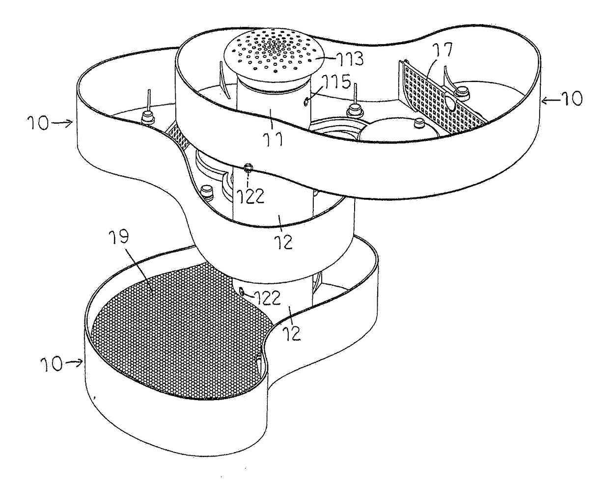
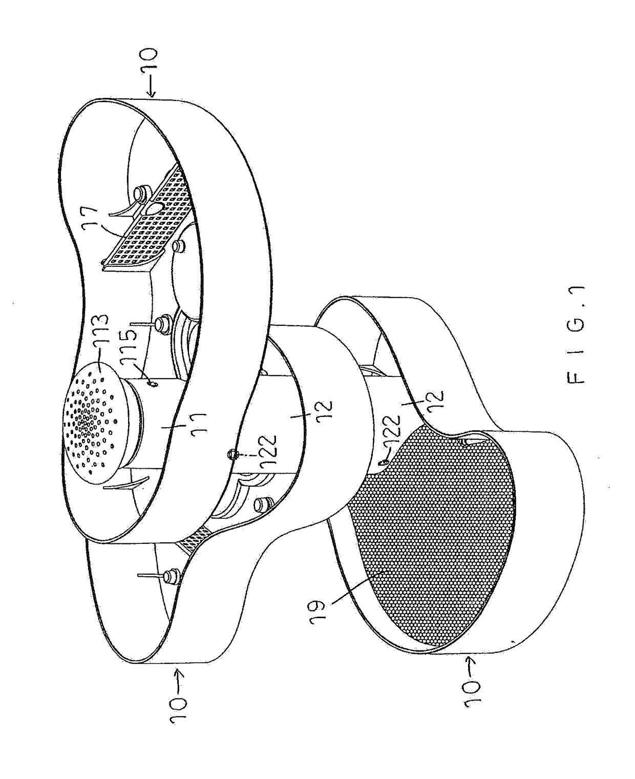
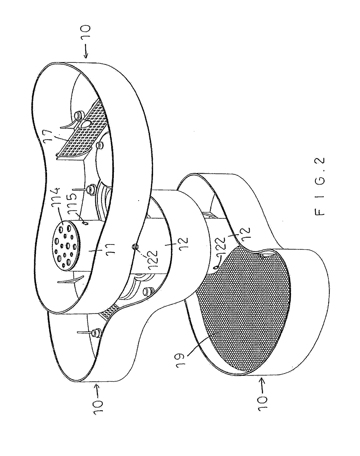
[0019]Referring to the drawings and initially to FIGS. 1-10, a tray structure in accordance with the preferred embodiment of the present invention comprises a plurality of trays 10 stacking together from top to bottom and expanding in an alternating manner to construct a spiral column-shaped plant tower.

[0020]Each of the trays 10 includes a bottom plate 101 and a peripheral wall 102 surrounding the bottom plate 101, with a cultivating space 103 being defined between the bottom plate 101 and the peripheral wall 102. The cultivating space 103 of each of the trays 10 is used to cultivate plants by water. Each of the trays 10 includes an inner tube 11 located at a first side of the bottom plate 101 and provided with a protruding locking member 111, and an outer tube 12 located at a second side of the bottom plate 101 and provided with a plurality of recessed locking members 121. The inner tube 11 of each of the trays 10 is received in the cultivating space 103 and surrounded by the peri...


PUM


Abstract

A tray structure includes a plurality of trays stacking together from top to bottom and expanding in an alternating manner to construct a spiral plant tower. Each of the trays includes a bottom plate, a peripheral wall and a cultivating space. Each of the trays includes an inner tube provided with a protruding locking member, and an outer tube provided with a plurality of recessed locking members. The recessed locking members of the outer tube of an upper one of the trays are locked onto the protruding locking member of the inner tube of a lower one of the trays. Each of the trays includes a connecting tube located in and connected with the inner tube by a plurality of separating ribs. The connecting tubes of the trays are juxtaposed to each other when the trays are combined together.

Description

BACKGROUND OF THE INVENTION1. Field of the Invention[0001]The present invention relates to a tray structure and, more particularly, to a tray structure for constructing a plant tower.2. Description of the Related Art[0002]A conventional plant wall structure comprises an upright wall and a plurality of baskets suspended on the upright wall for receiving plants (or vegetables) and soils. Thus, the plants present an outstanding appearance to enhance the aesthetic quality of the conventional plant wall. However, the baskets lacks variation of shapes and angles, thereby limiting the versatility of the conventional plant wall.BRIEF SUMMARY OF THE INVENTION[0003]In accordance with the present invention, there is provided a tray structure comprising a plurality of trays stacking together from top to bottom and expanding in an alternating manner to construct a spiral column-shaped plant tower. Each of the trays includes a bottom plate and a peripheral wall surrounding the bottom plate, with ...

Claims


Application Information

Patent Timeline
Patent Type & Authority Applications(United States)
IPC IPC(8): A01G9/12B65D21/02A01G9/10H04R1/02F21V23/00F21V33/00
CPCA01G9/029A01G9/12B65D21/0235A01G9/1073A01G2/20F21V23/002F21V33/0028F21Y2115/10H04R1/028A01G31/06F21W2121/00Y02P60/21
Inventor TSAI, SHENG-YUCAI, HAN-XI
Owner TSAI SHENG YU
Why Eureka
Try Eureka