Welding assembly for permanent joining of a first tubular component with a second component

a technology of tubular components and welding assemblies, which is applied in the direction of soldering auxiliaries, applications, and soldering apparatus, etc., can solve the problems of inability to conduct such operations, inability to fully weld the tube connector to the base tube, and inability to use welding robots to make such joints. the effect of reducing the time required for welding the tube connector

Active Publication Date: 2018-05-03
FRAUNHOFER GESELLSCHAFT ZUR FOERDERUNG DER ANGEWANDTEN FORSCHUNG EV +1
View PDF3 Cites 11 Cited by
  • Summary
  • Abstract
  • Description
  • Claims
  • Application Information

AI Technical Summary

Benefits of technology

[0012]The invention improves a welding assembly for permanently joining a first tubular component with a second, preferably also tubular component, along a two- or three-dimensional intersection curve, along which both components contact. The welding assembly comprises a securing assembly for detachably securely joining to a tubular end of the first component facing away from the intersection curve, a manipulator unit mounted directly or indirectly on the securing assembly such that it can pivot about a tube longitudinal axis assigned to the first component, the manipulator unit has a freely positionable manipulator end and comprises a welding tool attached to the freely positionable manipulator end so that the welding assembly is as flexible, compact and lightweight as possible and is capable of performing welding tasks particularly for producing tube joints on site without the need for the parts to be joined to have separate supports. In particular, it is possible to weld tube joint constellations of any kind which have at least one tube connector. The tube longitudinal axis forms an acute angle of 45° and less with the tube longitudinal axis of a base tube section. The welding assembly also makes possible for at least one welding tool to rotate through at least 360° about the tube longitudinal axis of the tube connector. Preferably the welding assembly can rotate infinitely often about the tube longitudinal axis, thus enabling the creation of at least one completely uninterrupted, homogeneous weld seam along the intersection curve, without the risk of colliding with surrounding tube wall areas. The unlimited revolutions of the welding tool about the tube longitudinal axis make possible welding large wall thicknesses up to several centimeters thick and having a correspondingly large weld seam filling volume to each other. In this context, the weld seam filling volume should be filled completely by the multiple single “weld beads” from an unlimited number of passes over the weld seam. Further, the welding assembly should be attachable securely yet detachably without additional installation to tube connectors which have differing tube diameters.
[0019]The at least one carrier ring of the carrier ring module, which is arranged to be rotatable by a motor relative to the clamping module, advantageously has a circular peripheral rim, along which at least one retaining device is attached and engages a linear frame in such manner that the linear frame is displaceable bidirectionally along a linear axis relative to the retaining device by an actuator. If a clamping module has been inserted in the first tubular component, the linear axis of the linear frame extends parallel to the tube longitudinal axis of the tubular first component, wherein the linear frame is positioned with the smallest possible radial separation from the outer wall of the first tubular component. As will be explained in the following, the actuator-driven operation of the linear frame is assured by a motorized spindle mechanism which is in engagement with the retaining device attached to the carried module to assure controlled, bidirectional displacement of the linear frame. The linear frame preferably has a truss reinforcing construction, which is extremely rigid and consequently has very low static deflection. The linear frame may be up to 4 meters long. On one end thereof the manipulator unit in the form of a kinematic chain, specifically in the form of a 6-axis vertical articulated robot, is arranged for further spatial positioning of the welding tool attached to the free end of kinematic chain. The spatially compact articulated robot has a dead weight of less than 100 kg, preferably about 60 kg, and is thus freely pivotable and positionable in space. In this way, both the articulated robot and the welding tool attached thereto may be pivoted completely around the tube connector as closely as possible on the outer wall of the tube connector, so that it is possible to produce a continuous weld seam along the join contour without colliding with the surrounding wall parts.
[0024]The welding assembly of the invention has a preferred way of connecting “tube joints” in which tube connectors with practically any diameter are to be welded to a base tube. The tube connectors may be arranged at practically any angle relative to the tube longitudinal axis of the base tube. A possible difficulty regarding collision between the welding assembly and the tube connector may be eliminated, since the welding assembly can be of compact construction with small dimensions. The modular construction of the welding assembly according to the invention means that two, three or more linear frames, each with manipulator units and the attached welding units can be mounted thereon can be fastened to the carrier ring module. This enables the welding time needed to fully weld a tube connector to a base tube to be reduced considerably.

Problems solved by technology

Due to the large dimensions and weights of the parts to be joined, both the weld seam preparation and the process of joining the tube joint connectors by welding are most often carried out manually, so production is lengthy, inefficient and expensive.
The use of welding robots to make tube joints of such kind is hindered by the large number of different tube connections.
It has not previously been possible to conduct such operations with a single automated universal welding assembly.
However, given the dimensions of the known welding assembly for attachment to the tube connector, it is only suitable for joining tube connectors to a base tube section with tube axes that are orientated orthogonally with respect to each other.
However this device is also associated with a disadvantage that handling of the tube components to be joined is limited by the size and weight of the components.
Moreover, tube joints with tube angle constellations in which the tube longitudinal axis of the tube connector is aligned at an angle less than 90°, and preferably less than 45° relative to the tube longitudinal axis of the base tube, present spatial challenges because the welding tool cannot be rotated 360° about the tube longitudinal axis of the tube connector to be welded because of the radially projecting construction.

Method used


Image

  • Welding assembly for permanent joining of a first tubular component with a second component
  • Welding assembly for permanent joining of a first tubular component with a second component
  • Welding assembly for permanent joining of a first tubular component with a second component

Examples


Embodiment Construction

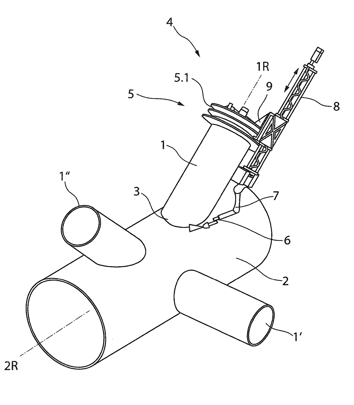
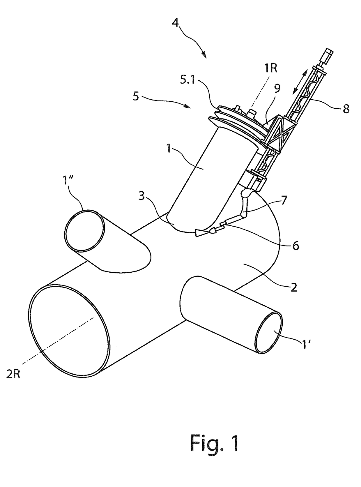
[0038]FIG. 1 is a schematic representation of a tube joint with a tube connector identified as first tubular component 1, having one frontal face which is or will be connected to a second tubular component 2, which is hereafter referred to as the base tube, along a three-dimensional intersection curve 3 by welding technology. Base tube 2 has a larger tube diameter than tube connector 1. Of course, it is possible that the tube diameters of the tube connector and the base tube have the same dimensions. The tube connector 1 illustrated in FIG. 1 has a tube longitudinal axis 1R, which is aligned at an angle less than 90°, preferably 45° relative to tube longitudinal axis 2R of base tube 2.

[0039]The welding process which joins tube connector 1 to base tube 2, is carried out with the welding assembly 4, which is attached solely to tube connector 1. That is a separate support for base tube 2 is not needed for the welding operation. Welding assembly 4 is braced exclusively against tube conn...


PUM

PropertyMeasurementUnit
angleaaaaaaaaaa
diametersaaaaaaaaaa
diametersaaaaaaaaaa

Abstract

The invention relates to a welding assembly for the permanent joining of a first tubular component with a second component along a two- or three-dimensional intersection curve, along which both components contact, comprising a securing assembly for detachably securely joining on a tubular end of the first component facing away from the intersection curve, a manipulator unit mounted directly or indirectly on the securing assembly such that it can pivot about a tube longitudinal axis assigned to the first component. The manipulator unit has a freely positionable manipulator end, with a welding tool attached to the freely positionable manipulator end. The securing assembly comprises a clamping module that can at least partially be introduced into the tubular end of the first component on the end side and in an axial manner. The clamping module is detachably securely to a tube inner wall of the first tubular component, as well as a carrier ring module which is rotatably attached to the clamping module, which axially extends beyond the tubular end of the first tubular component.

Description

CROSS-REFERENCE TO RELATED APPLICATIONS[0001]Reference is made to International Application No. PCT / EP2016 / 055623 filed Mar. 16, 2016, which is incorporated herein by reference in its entirety.BACKGROUND OF THE INVENTIONField of the Invention[0002]The invention relates to a welding assembly for permanent joining of a first tubular component with a second component along a two- or three-dimensional intersection curve, along which both components contact, comprising a securing assembly for detachably securely joining on a tubular end of the first component facing away from the intersection curve, a manipulator unit mounted indirectly or directly on the securing assembly such that it can pivot about a tube longitudinal axis of the first component, with the manipulator unit having a freely positionable manipulator end, and a welding tool attached to the freely positionable manipulator end.Description of the Prior Art[0003]The development of renewable energy sources has given rise to a g...

Claims


Application Information

Patent Timeline
Patent Type & Authority Applications(United States)
IPC IPC(8): B23K37/02B23K9/32B23K9/173B23K9/032
CPCB23K37/0276B23K37/0252B23K37/0241B23K37/0217B23K37/0282B23K9/327B23K9/173B23K9/032B23K2201/04B23K2203/04B23K9/32B23K37/0533B23K2101/04B23K2103/04
Inventor WANNER, MARTIN CHRISTOPHDRYBA, STEFFENWEIDEMANN, BJOERNHARMEL, ANDRE
Owner FRAUNHOFER GESELLSCHAFT ZUR FOERDERUNG DER ANGEWANDTEN FORSCHUNG EV
Why Eureka
Try Eureka