Electrically powered rotating subsea apparatus and method

a technology of electric motors and rotating subsea devices, which is applied in mechanical equipment, machines/engines, and gearing, etc., can solve the problems of increasing the time taken to scan a long structure such as a pipeline, increasing the wear on the apparatus, and increasing the time taken to scan significant lengths. , to achieve the effect of efficient scanning

Active Publication Date: 2018-05-03
TRACERCO LTD
View PDF15 Cites 1 Cited by
  • Summary
  • Abstract
  • Description
  • Claims
  • Application Information

AI Technical Summary

Benefits of technology

[0037]Preferably the method comprises rotating the detectors and the source about an angle of 360 degrees or more. That may be advantageous in that each scan position is effectively repeated, but with the source and detectors in opposite locations, at angular positions separated by 180 degrees. A 360 degree scan may therefore produce two measurements for each scan position. An advantage of the present invention is that continuous 360° scanning may be used.
[0038]Subsea locations may be locations at a depth of 100 m or greater, preferably 1000 m or greater, more preferably 3000 m or greater, yet more preferably 10000 ft (3048 m) or greater. Subsea locations may be locations at a depth in the range of 100 m to 1000 m, preferably 100 m to 3000 m, more preferably 1000 m to 3000 m or 1000 m to 10000 ft (3048 m). It will be appreciated that apparatus and methods suitable for use in deep water, for example at depths of 3000 m or 10000 ft (3048 m), may be suitable for use in shallower water, for example at depths of less than 3000 m. That may be, for example, because the hydrostatic pressure decreases with decreasing depth. However apparatus and methods suitable for use in shallow water, for example at depths of 1 m, may not be suitable for use in deeper water, for example water deeper than 1 m.
[0039]The method may be particularly advantageous in the scanning of subsea pipelines. It will be appreciated that subsea pipelines may be long structures, and that their integrity may be important to safe and environmentally responsible operation of subsea installations, but that the inspection of that integrity may be difficult to perform. The ability of the method of the invention to non-intrusively and efficiently scan significant lengths of pipeline, for example using continuous 360° scanning, may therefore be particularly advantageous.
[0040]The apparatus may be deployed using an ROV (remotely operated vehicle) at subsea locations and may be provided with clamping means to secure the apparatus to the subsea structure. The clamping means advantageously holds the first part of the apparatus in a fixed position relative to the subsea structure being scanned while a source and detectors are rotated about the subsea structure on the second part. Preferably the subsea structure is an elongate structure, for example a pipeline, having an axis, or at least a local axis for the section of the subsea structure where the apparatus is deployed, and the axis of rotation of the second part lies along the axis of the subsea structure. The scanning method may then be carried out at a plurality of circumferentially offset positions around the structure so that data may be acquired at a variety of angles through the structure. The apparatus may then be moved to a different location, preferably a different axial location, with respect to the structure and the measurement repeated. Information such as changes in density which may highlight flaws or other features within the structure can be obtained. In some embodiments the first or second part, or both parts, may be hingedly openable, for example in a clam shell arrangement wherein the part comprises a pivot and a releasable joint such that releasing the joint permits the part to swing open about the pivot. The mechanical transfer of power may be particularly advantageous in such embodiments since the elements of the mechanical transfer system, for example the toothed wheels, may be more able to operate robustly with a releasable joint in them than, for example, electrical connections.
[0041]Preferably the apparatus is provided with crawler apparatus for moving along the subsea structure. In that way the apparatus need only be deployed with an ROV at the start of the scanning process and can then be moved along the structure using the crawler apparatus provided.
[0042]Whilst the invention has been described above in relation to subsea operation and structure, it will be appreciated that aspects of the invention may also be advantageously deployed at other locations, for example onshore locations. In a third, broad aspect of the invention, there is provided an apparatus comprising:

Problems solved by technology

Stopping the apparatus and reversing the direction of rotation takes time and may increase wear on the apparatus.
However, a battery has limited capacity and must be recharged periodically.
Both of those techniques require the apparatus to cease operation, which may significantly increase the time taken to scan a lengthy structure such as a pipeline.
However, during the rotating scan process parts of the apparatus may pass underneath the structure.
If there were to be a failure of the drive mechanism when part of the apparatus is underneath the structure, it may not be possible to lift the apparatus off the structure.
It will be appreciated that such a manoeuvre may be challenging to perform.
In subsea applications, additional constraints arise.
Any increase in size of the apparatus can also result in significant increases in the force to which the apparatus is subject, since the high pressure of the water is then applied across a larger surface area.

Method used


Image

  • Electrically powered rotating subsea apparatus and method
  • Electrically powered rotating subsea apparatus and method
  • Electrically powered rotating subsea apparatus and method

Examples


Embodiment Construction

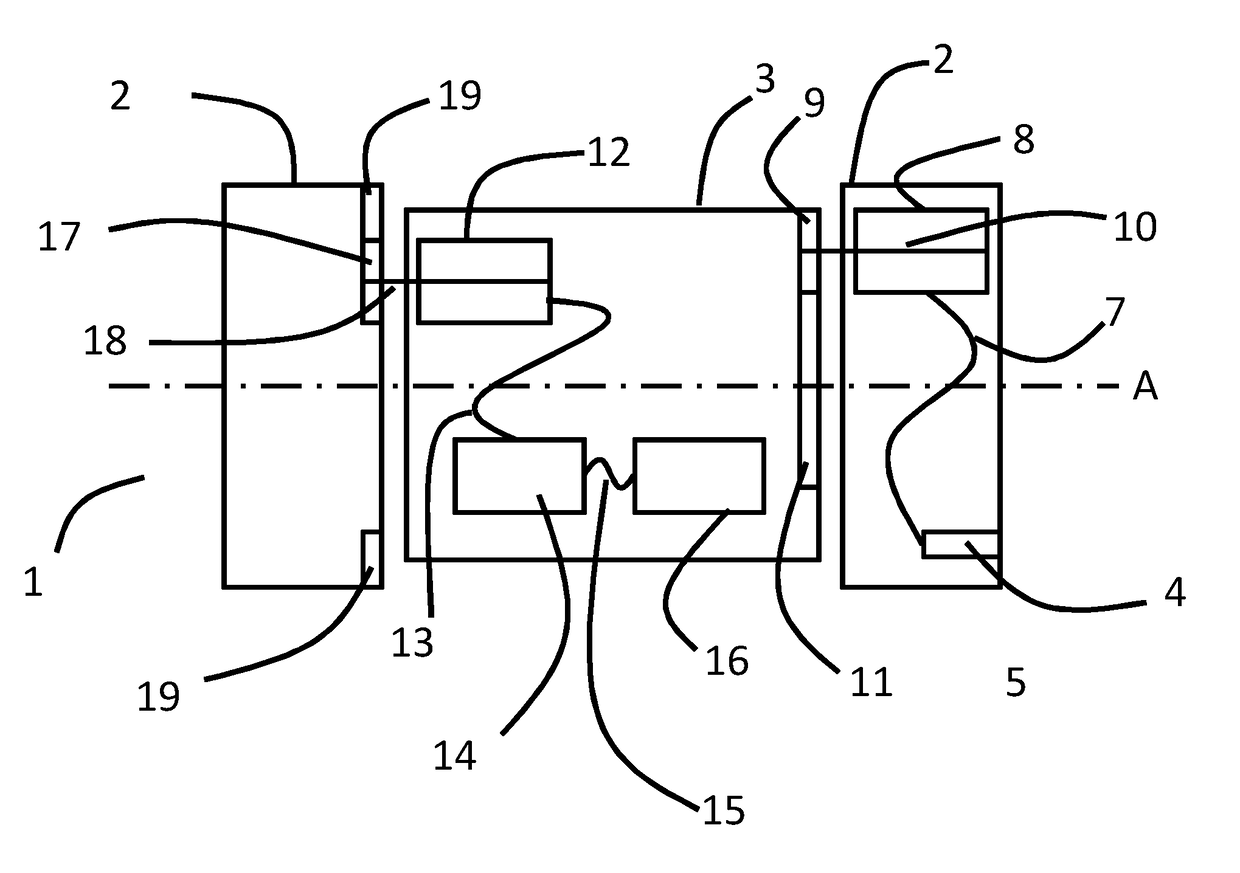
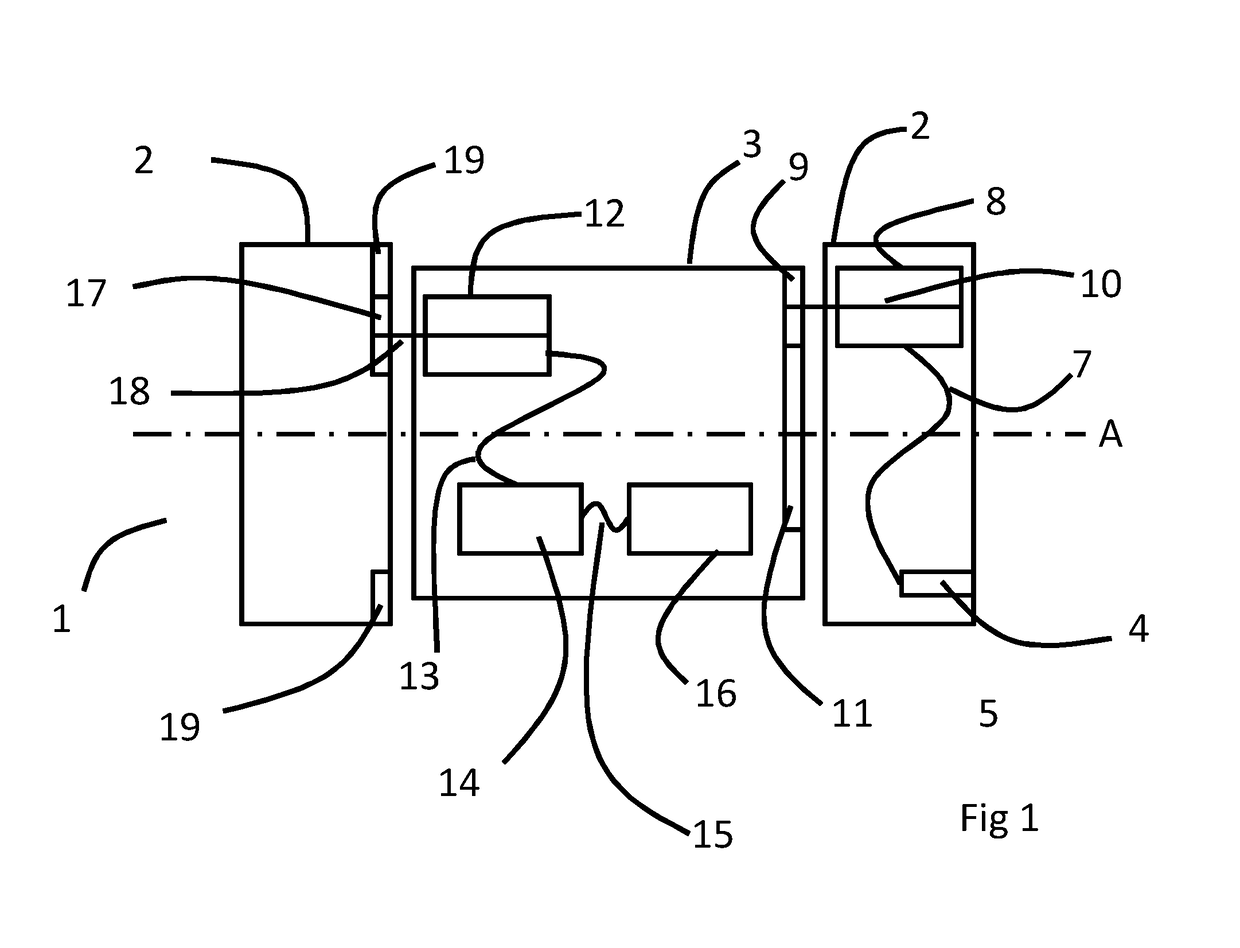
[0061]In FIG. 1, an apparatus 1 comprises a first part 2 (shown in FIG. 1 in two halves, with interconnecting members removed for clarity) and a second part 3, which is mounted on the first part 2 such that the second part 3 rotates relative to the first part 2 about axis A. A hydraulic power input connection 4 is mounted on the first part 2 and connected to hydraulic motor 8 by hydraulic line 7. Hydraulic motor 8 is mounted on the first part 2 and hydraulic line 7 can therefore be secured to first part 2 to keep it secure in subsea currents. Motor 8 includes drive shaft 10, on which is mounted drive wheel 9. Drive wheel 9 engages with driven wheel 11, which is fixed to the second part 3. Also mounted on second part 3 is generator 12, which is a subsea ROV thruster (such as those provided by Submertec) configured to operate as a generator. Generator 12 includes shaft 18 on which is mounted driver wheel 17. Driver wheel 17 engages with static wheel 19, which is fixed to the first par...


PUM


Abstract

A subsea apparatus (1, 201) is disclosed. The subsea apparatus (1, 201) comprises a first part (2, 202) and a second part (3, 203) rotatably mounted on the first part (2, 202). The second part (3, 203) comprises electrically powered components (16). A motor (8, 208) is mounted on the first part (2, 202) and configured to drive rotation of the second part (3, 203) relative to the first part (2, 202). The apparatus also comprises a generator (12, 212) mounted on the second part (3, 203) such that rotation of the second part (3, 203) relative to the first part (2, 202) drives the generator (12, 212) to generate power for the electrically powered components (16). A method of providing power to a rotating part of a subsea apparatus (1, 201) is also disclosed.

Description

FIELD OF THE INVENTION[0001]The present invention relates to a subsea apparatus and a method of generating power on a rotating part of a subsea apparatus. The apparatus and method of the invention have particular benefits for use in an undersea pipeline inspection apparatus.BACKGROUND[0002]In order to scan a subsea structure, such as a pipeline, it is known to mount an apparatus on the structure and then to rotate at least a part of the apparatus around the structure. An example of such an apparatus is described in GB 2496736 A. That apparatus comprises a source of gamma radiation and an array of detectors spaced apart circumferentially. The apparatus is capable of being arranged with the structure to be scanned, such as a pipeline, positioned between the source and detectors so that radiation emitted by the source can pass along the plurality of paths through a portion of the structure to the detectors. Counting the number of gamma photons transmitted from the source to the detecto...

Claims


Application Information

Patent Timeline
Patent Type & Authority Applications(United States)
IPC IPC(8): F03B13/10
CPCF03B13/10F16H1/06F05B2260/42F05B2270/107H02K5/132H02K7/116H02K11/35G01N23/06Y02E10/20
Inventor FEATONBY, PAUL DAVID
Owner TRACERCO LTD
Why Eureka
Try Eureka