Anti-barricade door stop

a door stop and anti-barricade technology, applied in the direction of carpet fasteners, dwelling equipment, building components, etc., can solve the problems of door stop binding, trapping or other injury risk,

Active Publication Date: 2018-05-10
SAFEHINGE
View PDF19 Cites 0 Cited by
  • Summary
  • Abstract
  • Description
  • Claims
  • Application Information

AI Technical Summary

Benefits of technology

[0023]It is a significant advantage of the invention that the door stop member is adapted such that initial movement of the door stop member is directly away from the face of the door (i.e. in the direction of the door will initially swing when the stop is released). This means that friction (e.g. static friction) between the door and the door stop member is unlikely to result in partial or complete jamming of the door stop member. Furthermore, it means that any force applied to the door by the barricade acts to push the door stop member into the retracted position, and this avoids the need for a user to manually (or otherwise actively) move the door stop. While in some cases the user may need to pull the door open by a handle or the like (e.g. if a barricade is blocking opening of the door but not pushing upon the door), the user should not have to touch the stop at any point.
[0024]Accordingly, the door stop member is adapted to at least initially move in a direction which avoids significant lateral movement across the face of the door. Excessive lateral movement results in an increased risk of the door stop binding against the face of the door, and also makes it necessary for a user to actively move the door stop (as opposed to the situation in the present invention where movement of the door typically acts to move the door stop without any need for active movement thereof). It will be understood that for a pivotably mounted door stop member the direction of movement will change as the door stop member pivots, and, as such, it is the initial movement which is most critical. As the member pivots and approaches, say 90 degrees, the movement will be substantially lateral to the face of the door, but at that point static friction will have ceased to exert an effect and the area of contact between the leading face of the door stop member and the face of the door will be minimal (the leading face of the door stop member will be at a slope relative to the face of the door)—thus further pivoting movement of the door stop member will not be affected by binding.
[0025]Suitably the door stop member is configured such that the initial movement is in a direction of from 50 to 130 degrees relative to the face of the door (i.e. 40 degrees either side of perpendicular to the face of the door), more preferably from 70 to 110 degrees, yet more preferably from 80 to 100 degrees relative to the face of the door. For completeness, in a geometric sense it will be understood that, where the door stop member is pivotably mounted on the door jamb, these angles refer to the angle made relative to the plane defined by the face of a door by a tangent to the curve through which the door stop pivots when moving from the extended to the retracted position, and where the point of tangency corresponds to the point on the curve at which the door stop is located when in the extended position.
[0026]In a preferred embodiment the stop initially moves in a direction which is substantially perpendicular to, and away from, the face of the door.
[0027]It will be appreciated that, where the door stop member is pivotably mounted on the door jamb, the initial movement of the door stop member relative to the door will depend on the position of the pivot point of the door stop member. Suitably the pivot point is located substantially in line with the leading face of the door stop member; this will result in an initial movement which is substantially perpendicular to the face of the door. The advantage of this is that the pivoting movement of the door stop member is away from the face of the door (i.e. in the direction of the door will initially swing when the stop is released), without any substantial movement away from the jamb (i.e. across the face of the door) being required. Alternatively, the pivot point can be located beyond the leading face of the door stop member (i.e. in the direction towards the door)—this will result in an initial angle movement which is somewhat towards the jamb. Alternatively, the pivot point can be located away from the leading face of the door stop member (i.e. somewhat away from the door)—this will result in an initial movement which is somewhat away from the jamb. However, it will be noted in the latter two cases that the initial movement of the door stop should not result in significant lateral movement which results in problems with friction or the need to actively move the door stop. It is generally preferable that the pivot point is positioned substantially flush with, or recessed into, the jamb.
[0028]It should be noted that, in general, references to the face of the door and the like are made with reference to the door in the closed position, i.e. when it abuts against the door stop member in normal use, unless the context dictates otherwise. This can also be referred to as the ‘zero position’ or ‘neutral position’. It should also be noted that the invention discusses the position of the door by way of convenience and clarity, but this does not mean that a door need actually be present in the invention; in several aspects of the invention the door jamb assembly need only be adapted for use in a door frame. A direction which is ‘away from the door’ or suchlike means the direction in which movement of the door from the closed position is normally limited by the door stop member (i.e. typically away from the room which the door opens). A direction which is ‘towards the door’ or suchlike means the direction from the closed position in which the door is free to move in normal use (i.e. typically into the room which the door opens).

Problems solved by technology

At best this requires a user to move the stop manually (which raises the risk of trapping or other injury), at worst it can result in binding of the door stop as a result of friction between the stop and the face of the door.

Method used


Image

  • Anti-barricade door stop
  • Anti-barricade door stop
  • Anti-barricade door stop

Examples


Embodiment Construction

[0085]While the making and using of various embodiments of the present invention are discussed in detail below, it should be appreciated that the present invention provides inventive concepts that can be embodied in a wide variety of specific contexts. The specific embodiments discussed herein are merely illustrative of specific ways to make and use the invention and do not delimit the scope of the invention.

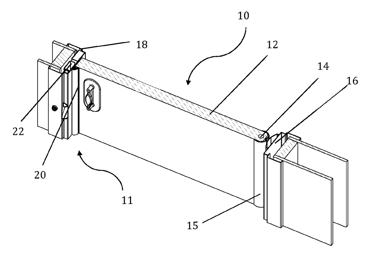
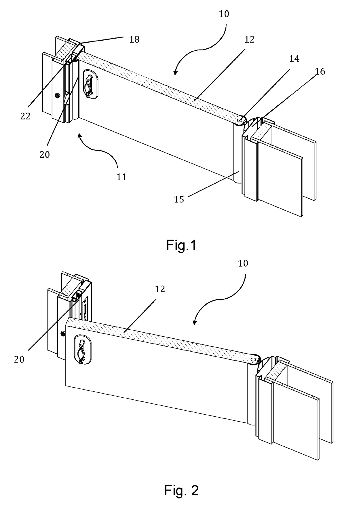
[0086]The present invention relates to a door assembly which is adapted to allow reversible modification of the door assembly from a single-swing mode of operation to a double-swing mode of operation when needed, e.g. in a barricade situation.

[0087]FIG. 1 shows a cross section of door assembly 10 which is an exemplary embodiment of the present invention. The door assembly 10 comprises a door 12, which is pivotably mounted in a frame via a double swing hinge 14. The two vertical door jambs (hinge side jamb 16 and latch side jamb 18) are shown.

[0088]As can be seen, the door has a ...


PUM


Abstract

The present invention relates to a door jamb assembly comprising a door stop member movably mounted thereon, configured such that the door stop is selectively operable to move from an extended, door-engaging position into a retracted door-disengaging position, and where the door stop member is adapted to initially move directly away from the face of a door with which it is in contact during use. Associated methods, door assemblies and suchlike are also provided. The door jamb assembly of the present invention is of particular use in situations where a door may be barricaded.

Description

[0001]The present invention relates to door systems which are adapted to assist in resolving a door barricade situation, e.g. when an obstruction has been put in place to prevent a door from opening. The invention relates to a door stop which in normal use prevents a door from swinging in both directions (i.e. creates a single swing door), but which when required, (e.g. when a barricade prevents the door opening in a first direction) is adapted to permit opening of the door in a second direction when required. The invention also relates to associated systems, methods and apparatuses.BACKGROUND OF THE INVENTION[0002]Doors barricades occur in various situations, but are particularly prevalent and of significant concern in mental health environments. In many cases a patient may obstruct a door (e.g. a bedroom door) to prevent it from swinging open. This may be done for various reasons, but in some cases the patient may wish to harm themselves or possibly commit suicide. In other cases ...

Claims


Application Information

Patent Timeline
Patent Type & Authority Applications(United States)
IPC IPC(8): E05B65/06E06B1/04E06B3/36E06B5/10
CPCE05B65/06E06B1/045E06B3/36E06B5/10E06B1/526Y10S292/15Y10T292/1043
Inventor IZOD, MARTINYOUNG, JEREMY
Owner SAFEHINGE
Why Eureka
Try Eureka