Clothing hanger stabilizer

a technology for clothing hangers and stabilizers, which is applied in the direction of clothing, garments, applications, etc., can solve the problems of reducing independence, requiring considerable effort and planning from people without complete use of their bodies, and reducing independence, so as to prevent forward movement of clothing hangers, stabilize clothing hangers, and facilitate manipulable latching

Inactive Publication Date: 2005-02-01
WRIGHT CYNTHIA A
View PDF12 Cites 4 Cited by
  • Summary
  • Abstract
  • Description
  • Claims
  • Application Information

AI Technical Summary

Benefits of technology

The hanger stabilizing side of the base faces inward toward the user. A hanger receptacle is formed, cut, or connected to the stabilizing side of the base. In a preferred embodiment, the hanger stabilizing side resembles a box-like shape with an arcuate, hook-shaped groove formed therein. Constructed in this manner, the hook portion of a conventional clothing hanger can be placed in the groove. Once positioned within the groove, a knob portion, bounded on the lower side by the groove, supports the weight of the hanger and any clothing hanging thereon. Desirably, this knob portion includes a lip, or rim, to prevent the hook of the clothing hanger from sliding forward off of the knob. The arcuately-shaped groove, in combination with the knob portion, serves to stabilize the clothing hanger. Thus, when placed over the knob portion and with the hook situated within the groove, a conventionally shaped hanger is restrained from substantial lateral movement within the plane that is parallel to the wall on which the base is mounted. The hanger, then, will not rock about the knob portion. The extent of movement of the hanger will, however, depend upon the size and geometry of the particular hanger and the width of the groove formed in the base.
Unlike so many other devices for use by physically-challenged individuals that limit the holding of only a single item, the device of the present invention allows a physically-challenged or restrained person to sequentially position hangers on the base one at a time while dressing or undressing. For instance, a hanger may be positioned in the base, an article of clothing hanged thereon, and the hanger removed and placed in a closet, or vice versa. All of these steps may be performed with the use of only one extremity.
Another aspect of the present invention is to provide a device for stabilizing a clothing hanger that includes a cover for preventing forward movement of a hanger and that also may be decorative. The base and receptacle combination described above, therefore, also includes a cover that is adapted to cover the stabilizing side of the base, and the arcuate groove, in articular. In one preferred construction, the cover is dimensioned to hingedly fit over the ace, or stabilizing side, of the base. Preferably, the back of the front cover securely latches to the base by means of a magnetic catch, or other easily manipulable latching mechanism. The cover performs at least two functions; it assists in preventing the hanger hook from sliding off of the base, and it may perform an ornamental function so that the underlying base is essentially hidden from view. The cover then may even comprise an ornamental picture frame or other holder for memorabilia.

Problems solved by technology

Simple tasks that are taken as routine and without a great deal of thought or planning by people require considerable effort and forethought on the part of those without complete use of their bodies.
In many instances, these daily tasks are impossible to complete.
As a result, such persons often require human assistance in performing such tasks, which reduces independence.
Such devices, however, do not address the problem associated with using conventional clothes hangers by a person without the full use of both arms or hands.

Method used


Image

  • Clothing hanger stabilizer
  • Clothing hanger stabilizer
  • Clothing hanger stabilizer

Examples


Embodiment Construction

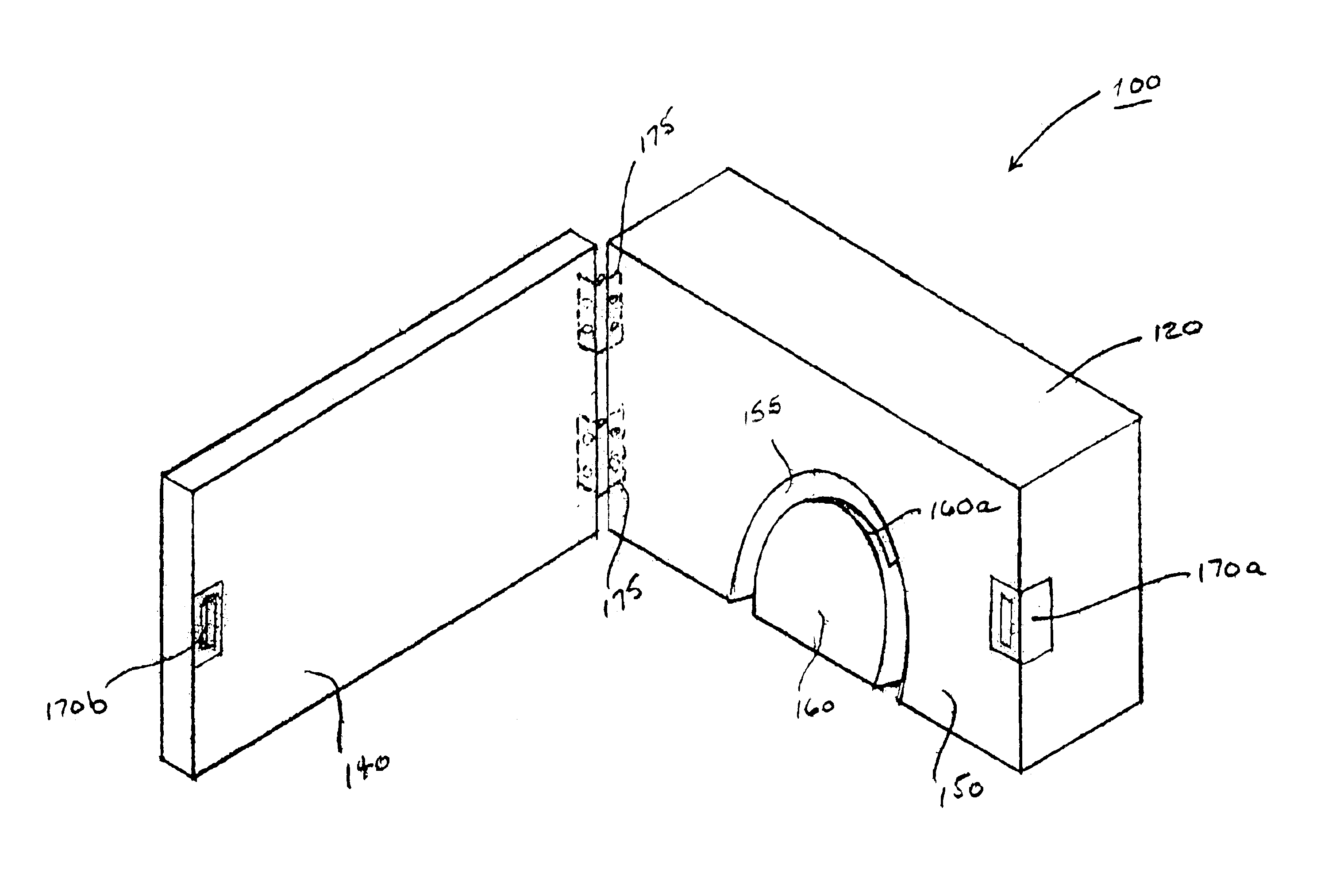
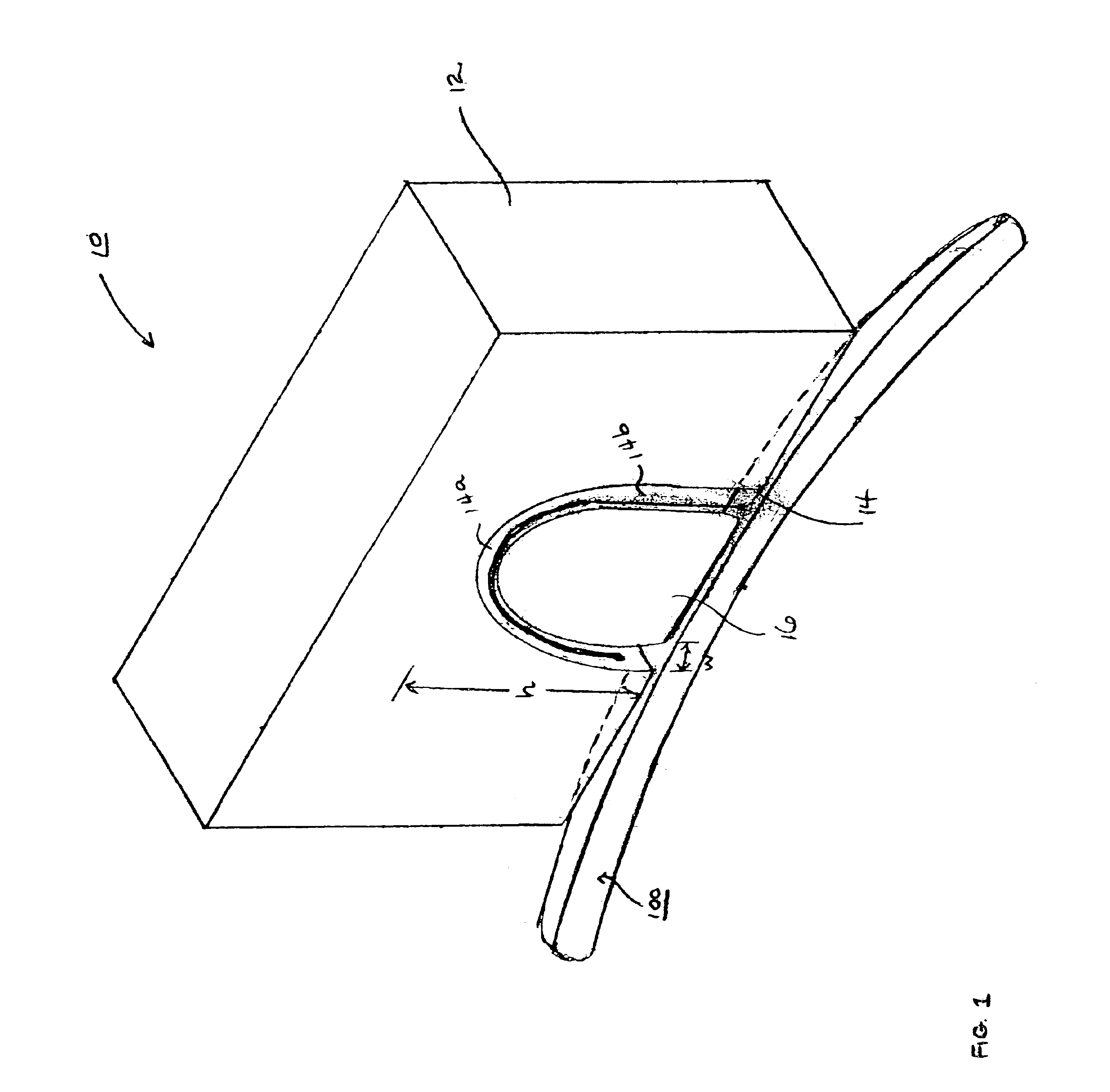
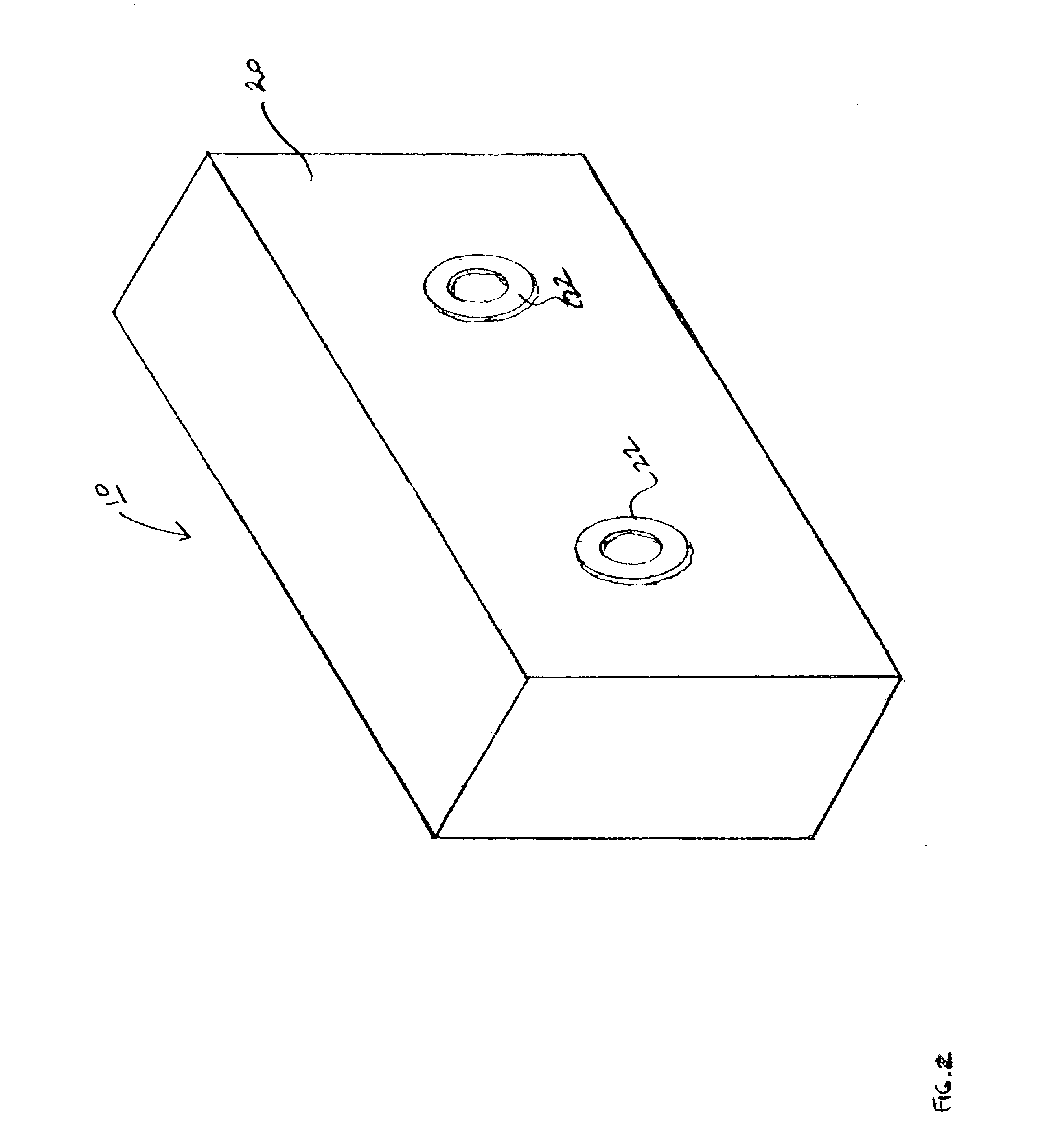
As shown in FIG. 1, one embodiment of the present invention is directed to a clothing hanger stabilizing device, shown generally as 10. The device, in its simplest construction, includes a mountable base 12 having a hanger-stabilizing receptacle, or knob, 16 thereon.

While the mountable base 12 is shown as a generally-rectangular box, its geometry is not limited thereto. Rather, the mountable base 12 may be constructed in an almost unlimited number of shapes and sizes. The mountable base 12 must be mountable to either a firm surface, such as a wall, or other sufficiently stable platform, pedestal, etc., and must be capable of holding and supporting a conventional type clothing hanger described hereinbelow. The mountable base 12 may be formed from a solid piece of stock material, such as wood, or may be metallic, plastic, etc. There is no requirement that the base be of a solid construction so long as it is sufficiently stable and rigid. The material type is also not critical to the p...


PUM


Abstract

A device for supporting and stabilizing a clothing hanger so that a user employing only one extremity can position a hanger thereon for hanging or removing an article of clothing without other assistance, comprising a base and a hanger receptacle that is configured and adapted to receive and stabilize a clothing hanger.

Description

FIELD OF THE INVENTIONThe present invention relates to the field of hanger or support devices for securing clothing, and, more particularly to a clothing hanger stabilizer that enables users to hang clothing thereon or remove clothing therefrom using only one extremity.BACKGROUND OF THE INVENTIONPhysically-challenged persons face a myriad of obstacles on a daily basis that most non-handicapped persons take for granted. Simple tasks that are taken as routine and without a great deal of thought or planning by people require considerable effort and forethought on the part of those without complete use of their bodies. In many instances, these daily tasks are impossible to complete. As a result, such persons often require human assistance in performing such tasks, which reduces independence.Over the years, a variety of devices have been conceived and developed for assisting physically-challenged persons in per-forming various functions. Such devices have been directed to mobility, lifti...

Claims


Application Information

Patent Timeline
Patent Type & Authority Patents(United States)
IPC IPC(8): A47G25/32A47G25/00A47G25/06
CPCA47G25/32A47G25/06
Inventor WRIGHT, CYNTHIA A.
Owner WRIGHT CYNTHIA A
Why Eureka
Try Eureka