
Air bag device for driver's seat

a technology for air bags and drivers, which is applied in the direction of pedestrian/occupant safety arrangements, vehicular safety arrangments, vehicle components, etc., can solve the problems of excessive tilting of the steering column, and increasing the injury of the driver's chest, so as to prevent or reduce the injury of the driver and prevent the increase of the injury

Active Publication Date: 2018-05-17
HYUNDAI MOBIS CO LTD
View PDF12 Cites 0 Cited by
  • Summary
  • Abstract
  • Description
  • Claims
  • Application Information

AI Technical Summary

Benefits of technology

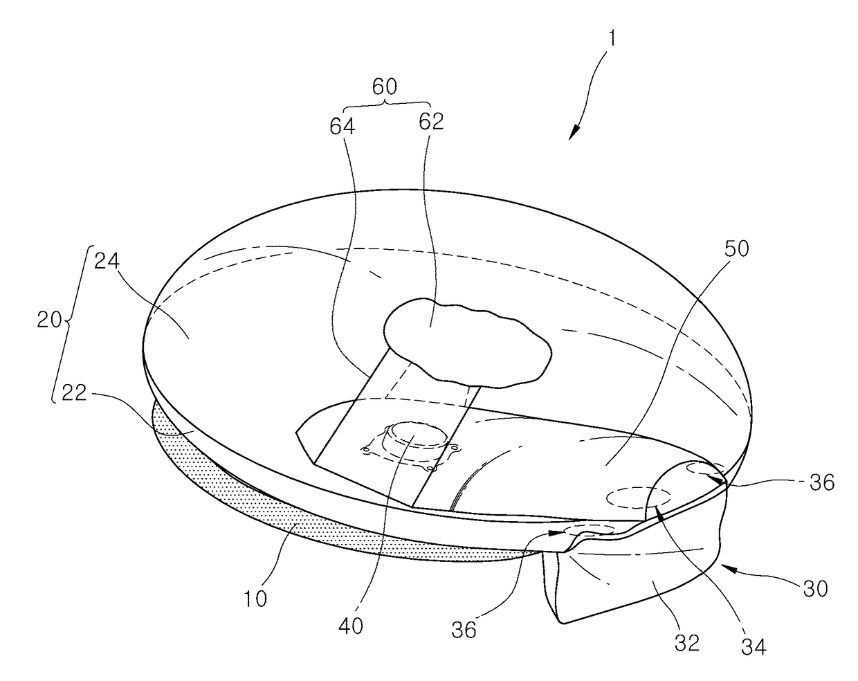
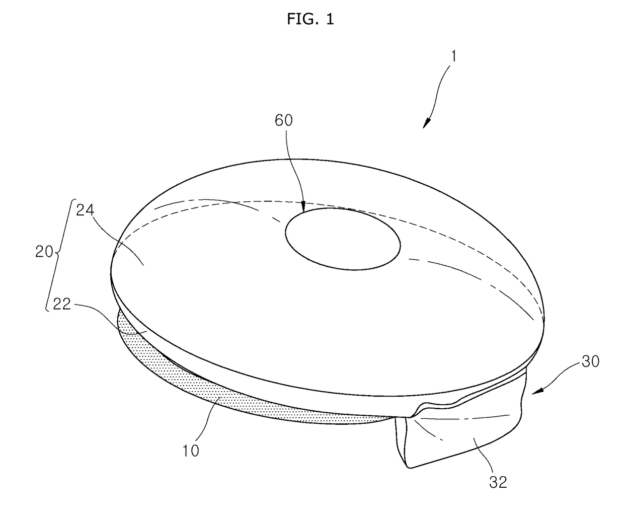
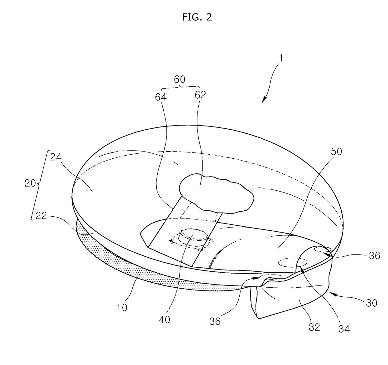
The present invention is an air bag device for a driver's seat that is designed to prevent or reduce injury caused by a collision with the steering wheel. It uses a sub-cushion unit that is deployed between the steering wheel and the driver's chest in the event of a head-on collision. The device has a guide chamber that allows gas produced by the inflator to flow and primarily deploy the sub-cushion unit, followed by flow to a main-cushion unit to secondarily deploy it. This prevents an injury from increasing while the driver's chest comes into contact with the steering wheel. Overall, the device helps to protect the driver in the event of a collision and reduces the risk of injury.

Problems solved by technology

Since a commercial vehicle is short in front overhang, a steering column may be excessively tilted up in the event of a head-on collision.
While the air bag for the driver's seat is lifted simultaneously with the steering column, an injury to a driver's chest increases.
Thus, the driver's chest and the steering wheel collide directly with each other, so that the driver's injury may be increased.

Method used


Image

  • Air bag device for driver's seat
  • Air bag device for driver's seat
  • Air bag device for driver's seat

Examples


Embodiment Construction

[0026]Hereafter, an air bag device for a driver's seat in accordance with embodiments of the invention will be described in detail with reference to the accompanying drawings. It should be noted that the drawings are not to precise scale and may be exaggerated in thickness of lines or sizes of components for descriptive convenience and clarity only.

[0027]Furthermore, the terms as used herein are defined by taking functions of the invention into account and can be changed according to the custom or intention of users or operators. Therefore, definition of the terms should be made according to the overall disclosures set forth herein.

[0028]FIG. 1 is a perspective view schematically illustrating the appearance of an air bag device for a driver's seat in accordance with an embodiment of the present invention, FIG. 2 is a view schematically illustrating the main configuration of the air bag device for the driver's seat in accordance with the embodiment of the present invention, FIG. 3 is...


PUM


Abstract

An air bag device for a driver's seat may include a main-cushion unit provided on a steering wheel and having a front chamber that comes into contact with the steering wheel and a rear chamber that faces a driver, a sub-cushion unit communicating with the main-cushion unit and protruding outwards from the main-cushion unit, and a guide chamber located in the main-cushion unit to define a passage for guiding gas produced in an inflator to the sub-cushion unit.

Description

CROSS-REFERENCES TO RELATED APPLICATIONS[0001]The present application claims priority to Korean application number 10-2016-0152977, filed on Nov. 16, 2016, which is incorporated by reference in its entirety.BACKGROUND OF THE INVENTION[0002]The present invention relates to an air bag device for a driver's seat, and more particularly, to an air bag device for a driver's seat, which has a cushion deployed between a steering wheel and a driver's chest in the event of a head-on collision of a vehicle, thus preventing a driver's injury.[0003]In general, air bag systems of vehicles are devices that instantaneously inflate air bags in the event of a collision to reduce injuries due to impacts, separately from a seat belt for restraining a person.[0004]Among the air bag systems, an air bag system for a driver is a device that instantaneously inflates an air bag between the driver and a steering wheel in the event of a vehicle collision to reduce injuries due to impacts.[0005]The driver air b...

Claims


Application Information

Patent Timeline
Patent Type & Authority Applications(United States)
IPC IPC(8): B60R21/233B60R21/203B60R21/2338
CPCB60R21/233B60R21/203B60R21/2338B60R2021/23382B60R21/264B60R2021/2648B60R2021/0004B60R2021/0044
Inventor KIM, DO HYOUNGPARK, HAE KWONKO, SEOKHOON
Owner HYUNDAI MOBIS CO LTD
Learn More