Biasing system for harrows

a harrow and biasing technology, applied in the field of agricultural implements, can solve the problems of significant force exerted by the tines against the surface of the field, inconsistent harrowing effect on the field surface,

Active Publication Date: 2018-05-24
BOURGAULT INDS
View PDF1 Cites 6 Cited by
  • Summary
  • Abstract
  • Description
  • Claims
  • Application Information

AI Technical Summary

Benefits of technology

[0018]The present disclosure provides a harrow implement where the downward tine force is maintained at a constant value as the harrow sections move up and down in response to changes in terrain. The tine force can be set while travelling along a field at any force in a range from zero to a maximum tine force determined by the maximum bias pressure available or desirable. Incre

Problems solved by technology

The downward force exerted by the harrow tines on the ground then varies resulting in an inconsistent harrowing effect on the field surface.
In the typical harrow implements of the prior art, the minimum downward bias force that can be provided is accomplished by ad

Method used


Image

  • Biasing system for harrows
  • Biasing system for harrows
  • Biasing system for harrows

Examples


Embodiment Construction

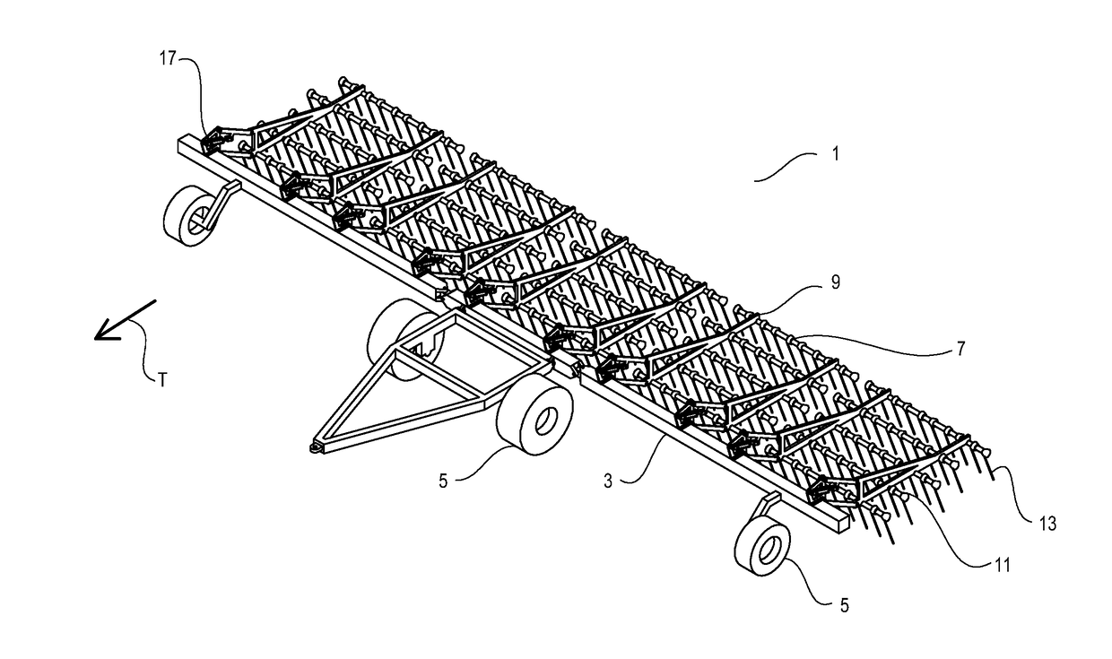
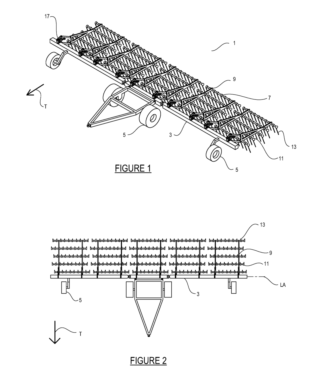
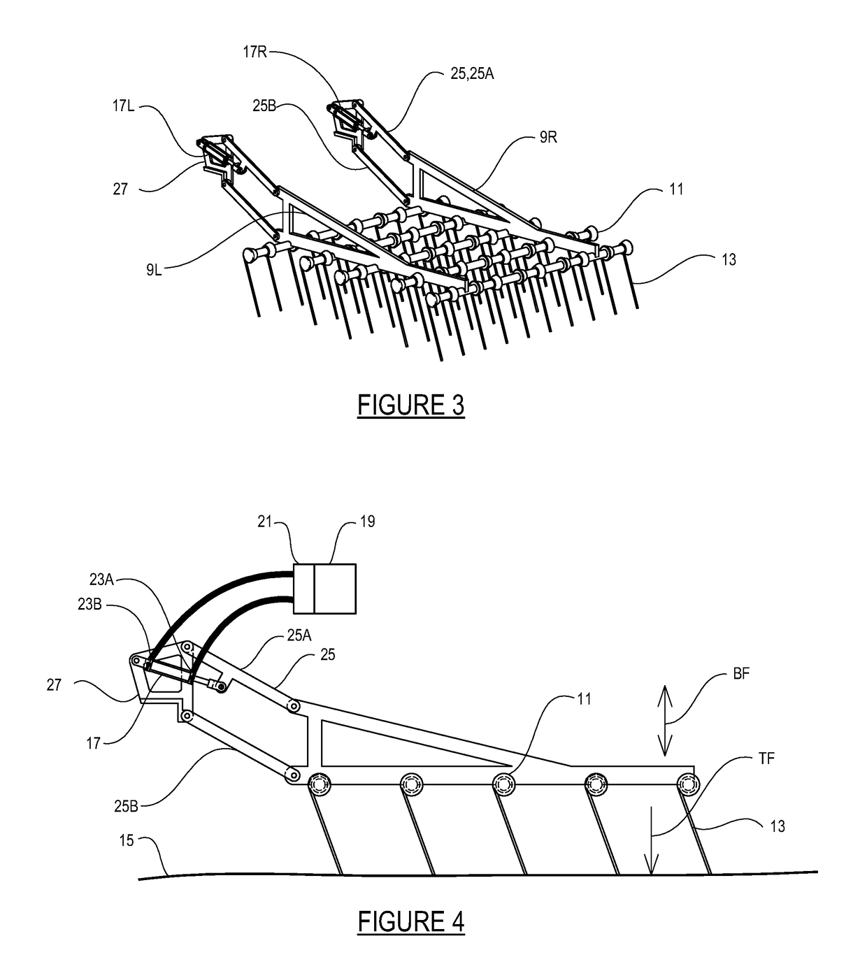
[0031]FIGS. 1-4 schematically illustrate an embodiment of a harrow implement 1 of the present disclosure. The implement 1 comprises a tool bar 3 mounted on wheels 5 for travel along a ground surface in an operating travel direction T that is perpendicular to a longitudinal axis LA of the tool bar 5. Harrow sections 7 are movably mounted to the tool bar 3 such that each harrow section 7 extends rearward from the tool bar 3 and is movable up and down with respect to the tool bar 3 independent of adjacent harrow sections 7.

[0032]Each harrow section 7 comprises rearward extending frame arms 9, and a plurality of support bars 11 attached to the frame arms 9. The support bars 11 are oriented perpendicular to the frame arms 9 and perpendicular to the operating travel direction T, and are spaced along the frame arms 9. Flexing harrow tines 13 are attached to each support bar 11, and the support bars 11 are rotatable with respect to the frame arms 9 to adjust the tine angle of the harrow tin...


PUM


Abstract

A harrow implement comprises a tool bar and harrow sections extending rearward therefrom. Each of a plurality of hydraulic cylinders is connected between the tool bar and a corresponding harrow section. A hydraulic control is operative to supply pressurized hydraulic fluid such that the hydraulic cylinders exert a substantially constant selected bias force on the harrow sections. The hydraulic control is operative to direct pressurized hydraulic fluid into a first port on each hydraulic cylinder to exert a downward bias force on the plurality of harrow sections, and operative to direct pressurized hydraulic fluid into a second port on each hydraulic cylinder to exert an upward bias force on the plurality of harrow sections. The hydraulic cylinder can be configured to raise the harrow sections to an idle position above the ground, and to a transport position extending up from the tool bar.

Description

CROSS-REFERENCE TO RELATED APPLICATION[0001]This application claims priority to and benefit of CA Serial No. 2,949,080, filed Nov. 21, 2016, the contents of which are incorporated by reference in their entirety for all purposes.FIELD OF THE INVENTION[0002]This disclosure relates to the field of agricultural implements and in particular a biasing apparatus for harrows on a harrow drawbar implement.BACKGROUND[0003]A conventional harrow implement includes a tool bar extending perpendicular to the implement's operating travel direction and a plurality of harrow sections extending rearward from the tool bar and movably mounted to the tool bar such that the harrow sections can move up and down so the harrow tines thereof can bear against the ground. The tool bar typically has a center section and right and left wing sections which can be folded, typically rearward, to a transport position.[0004]A typical harrow section comprises rearward extending frame arms, and a plurality of support ba...

Claims


Application Information

Patent Timeline
IPC IPC(8): A01B19/10A01B61/00A01B19/04A01B63/32
CPCA01B19/10A01B63/32A01B19/04A01B61/00A01B63/28
Inventor LUNG, DEVINDRAYTON, JESSE
Owner BOURGAULT INDS
Why Eureka
Try Eureka