Turbine engine and method of cooling thereof

a technology of turbine engines and cooling methods, applied in the field of turbine engines, can solve the problems of reducing the service life of electrical and electronic components in the undercowl space, and being particularly sensitiv

Active Publication Date: 2018-05-31
GENERAL ELECTRIC CO
View PDF2 Cites 1 Cited by
  • Summary
  • Abstract
  • Description
  • Claims
  • Application Information

AI Technical Summary

Benefits of technology

[0003]In one aspect, a turbine engine is provided. The turbine engine includes a core engine cowl including a compartment, a cooling airflow source positioned within the compartment, and a full authority digital engine control (FADEC) system coupled in communication with the cooling airflow source. The FADEC system is configured to determine a flight status of the turbine engine, and actuate the cooling airflow source when the turbine engine is not in flight, and before the turbine engine has been shut down, such that heat is exhausted from the compartment.
[0004]In another aspect, a cooling system for use within a core engine cowl of a turbine engine is provided. The cooling system includes a cooling fan positioned within a compartment of the core engine cowl, and a full authority digital engine control (FADEC) system coupled in communication with the cooling fan. The FADEC system is configured to determine a flight status of the turbine engine, and actuate the cooling fan when the turbine engine is not in flight, and before the turbine engine has been shut down, such that heat is exhausted from the compartment.

Problems solved by technology

In addition, other known electronic components, including full authority digital engine control (FADEC) systems, may be particularly sensitive to increasing engine core compartment temperatures both during gas turbine engine operation and as a result of soak-back after engine shutdown.
The high temperatures can have undesirable effects on and result in a reduced service life of the electrical and electronic components in the undercowl space.

Method used


Image

  • Turbine engine and method of cooling thereof
  • Turbine engine and method of cooling thereof
  • Turbine engine and method of cooling thereof

Examples


first embodiment

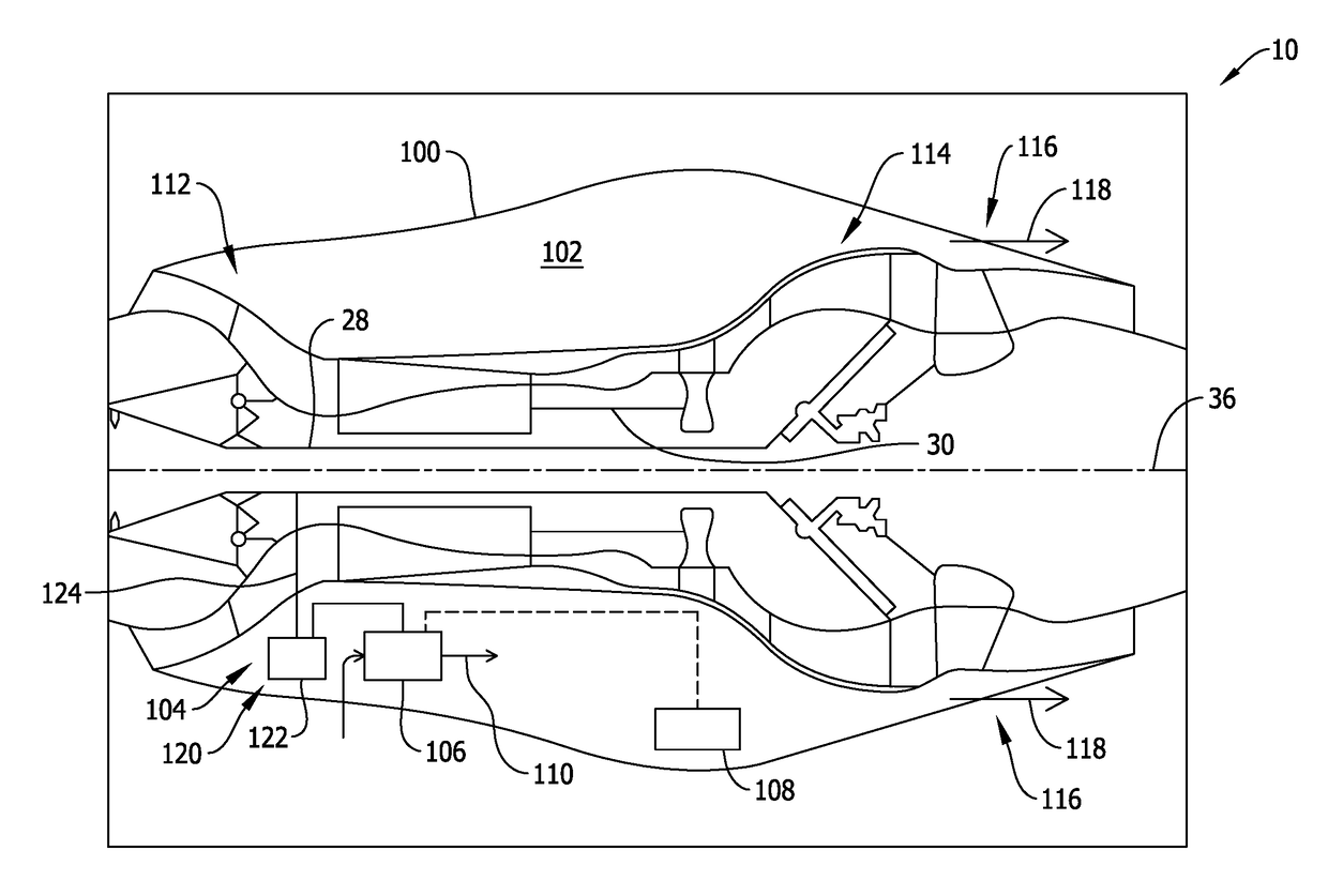
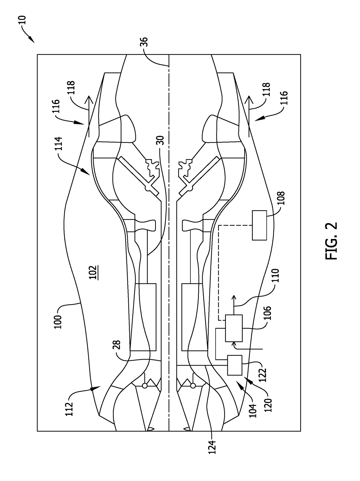
[0022]FIG. 2 is a schematic illustration of a portion of turbine engine 10 (shown in FIG. 1), in accordance with the disclosure. In the exemplary embodiment, turbine engine 10 further includes a core engine cowl 100 having a hollow compartment 102 that houses one or more mechanical or electronic components therein. For example, in one embodiment, a cooling system 104 is positioned within hollow compartment 102. Cooling system 104 includes a cooling airflow source, such as at least one cooling fan 106 positioned within hollow compartment 102, and a full authority digital engine control (FADEC) system 108 coupled in communication with cooling fan 106. FADEC system 108 is coupled, either by wired or wirelessly connectivity, in communication with one or more subsystems or components of turbine engine 10 and cooling system 104 to control the operation of turbine engine 10 and cooling system 104 at a predetermined stage of operation of turbine engine 10, as will be explained in more detai...

second embodiment

[0027]FIG. 3 is a schematic illustration of a portion of turbine engine 10 (shown in FIG. 1), in accordance with the disclosure. In the exemplary embodiment, as described above, cooling fan 106 is configured to operate for a preset time after turbine engine 10 has been shut down. For example, cooling fan 106 includes timer device 120 that shuts down cooling fan 106 at a time after actuation of cooling fan 106. In one embodiment, timer device 120 is an electronic timer 126 having an independent power supply 128. Independent power supply 128 enables electronic timer 126 to operate independent of FADEC system control. In some embodiments, independent power supply 128 also powers cooling fan 106 such that cooling fan 106 is operable after turbine engine shutdown.

third embodiment

[0028]FIG. 4 is a schematic illustration of a portion of turbine engine 10 (shown in FIG. 1), in accordance with the disclosure. In the exemplary embodiment, cooling system 104 further includes an airflow conduit 130 extending from cooling fan 106. More specifically, airflow conduit 130 includes an inlet 132 and a discharge outlet 134. Airflow conduit 130 is oriented such that cooling airflow 110 is received at inlet 132, channeled through airflow conduit 130, and discharged towards predetermined high temperature regions within core engine cowl 100. For example, as described above, hollow compartment 102 houses one or more electronic components therein, such as FADEC system 108. As such, in the exemplary embodiment, discharge outlet 134 is positioned such that cooling airflow 110 is channeled towards FADEC system 108 in a more efficient and direct manner. In an alternative embodiment, only a portion of cooling airflow 110 discharged from cooling fan 106 is channeled through airflow ...


PUM


Abstract

A turbine engine including a core engine cowl including a compartment, a cooling airflow source positioned within the compartment, and a full authority digital engine control (FADEC) system coupled in communication with the cooling airflow source. The FADEC system is configured to determine a flight status of the turbine engine, and actuate the cooling airflow source when the turbine engine is not in flight, and before the turbine engine has been shut down, such that heat is exhausted from the compartment.

Description

BACKGROUND[0001]The present disclosure relates generally to turbine engines and, more specifically, to cooling systems for cooling compartments and components of turbine engines after shutdown.[0002]Gas turbine engines typically include an undercowl space or engine core compartment as a part of the engine architecture. As gas turbine engines are improved to, for example, provide higher aircraft speed or lower specific fuel consumption (SFC), pressure ratios of fans and compressors and internal temperatures are expected to rise substantially, resulting in higher temperature for the engine core compartment and components. Engine core compartment components include electronics and other line replaceable units (LRUs). In addition, other known electronic components, including full authority digital engine control (FADEC) systems, may be particularly sensitive to increasing engine core compartment temperatures both during gas turbine engine operation and as a result of soak-back after eng...

Claims


Application Information

Patent Timeline
Patent Type & Authority Applications(United States)
IPC IPC(8): F02C9/18F02C3/04F01D25/24F02K3/06F02C7/18
CPCF02C9/18F02C3/04F01D25/24F02K3/06F05D2270/112F05D2220/32F05D2260/20F05D2270/52F02C7/18F01D21/12F01D25/14Y02T50/60
Inventor MONIZ, THOMAS ORYGLOVER, JEFFROSE, JOSEPHCLEMENTS, JEFFREY DONALD
Owner GENERAL ELECTRIC CO
Why Eureka
Try Eureka