
Aft flowing serpentine cavities and cores for airfoils of gas turbine engines

Active Publication Date: 2018-06-07
RAYTHEON TECH CORP
View PDF2 Cites 22 Cited by
  • Summary
  • Abstract
  • Description
  • Claims
  • Application Information

AI Technical Summary

Benefits of technology

The patent describes a new design for airfoils in gas turbine engines that includes a hybrid aft flowing serpentine cavity. This cavity is formed by a combination of a skin core and a plurality of core bodies that are positioned around the airfoil. The core bodies can include a radial flow core and a leading edge hybrid skin core, as well as other features like trip strips, turbulators, and pedestals. The airfoil also includes a plurality of cooling cavities that are positioned about the hybrid aft flowing serpentine cavity to form a shielding structure and improve cooling efficiency. The technical effects of this design include improved cooling performance, reduced weight, and improved durability of the airfoil.

Problems solved by technology

Clearance, abrasion and temperature effects are of concern proximate the tip region of the airfoil.

Method used


Image

  • Aft flowing serpentine cavities and cores for airfoils of gas turbine engines
  • Aft flowing serpentine cavities and cores for airfoils of gas turbine engines
  • Aft flowing serpentine cavities and cores for airfoils of gas turbine engines

Examples


Embodiment Construction

[0044]A detailed description of one or more embodiments of the disclosed apparatus and method are presented herein by way of exemplification and not limitation with reference to the Figures.

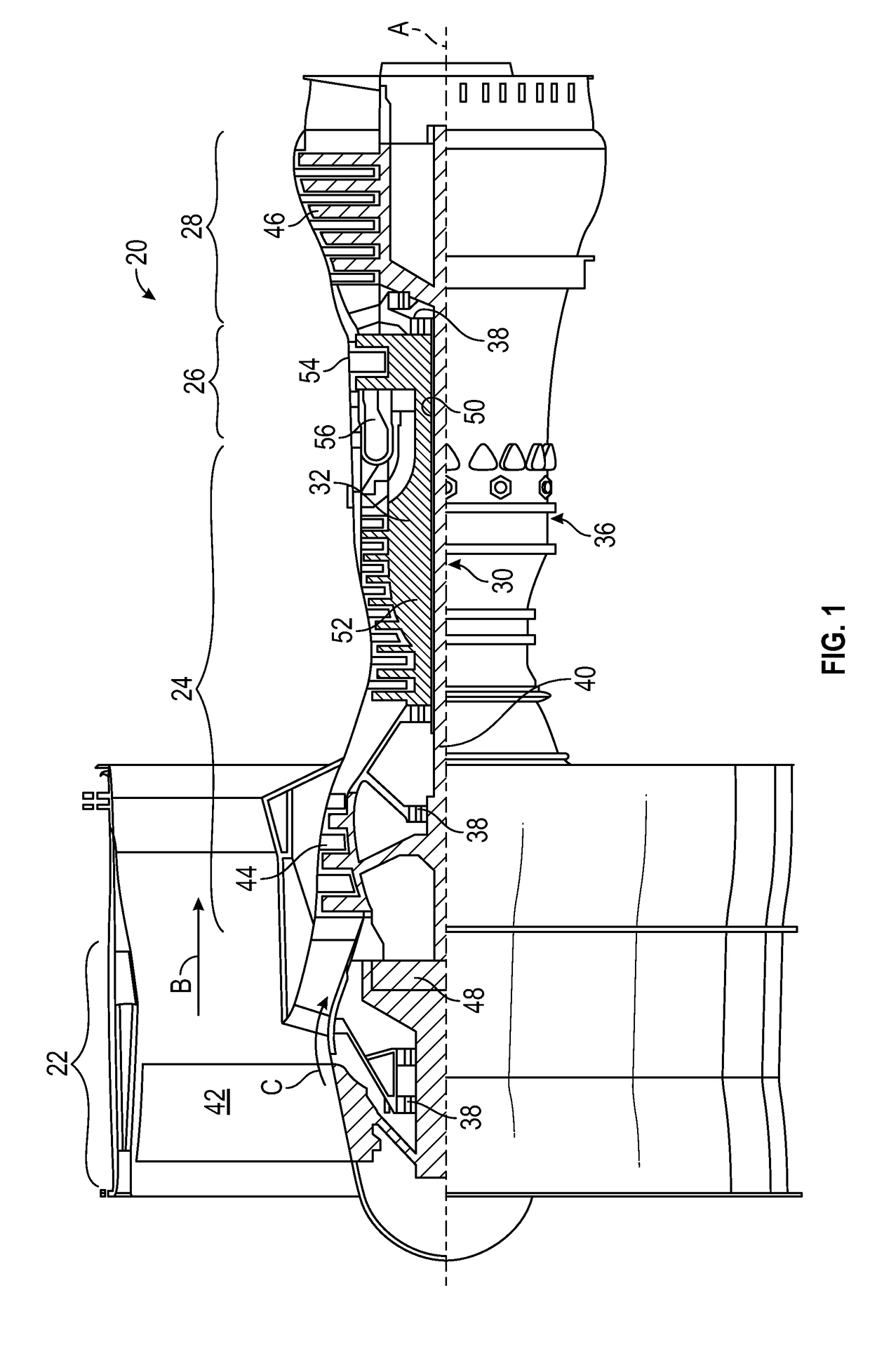
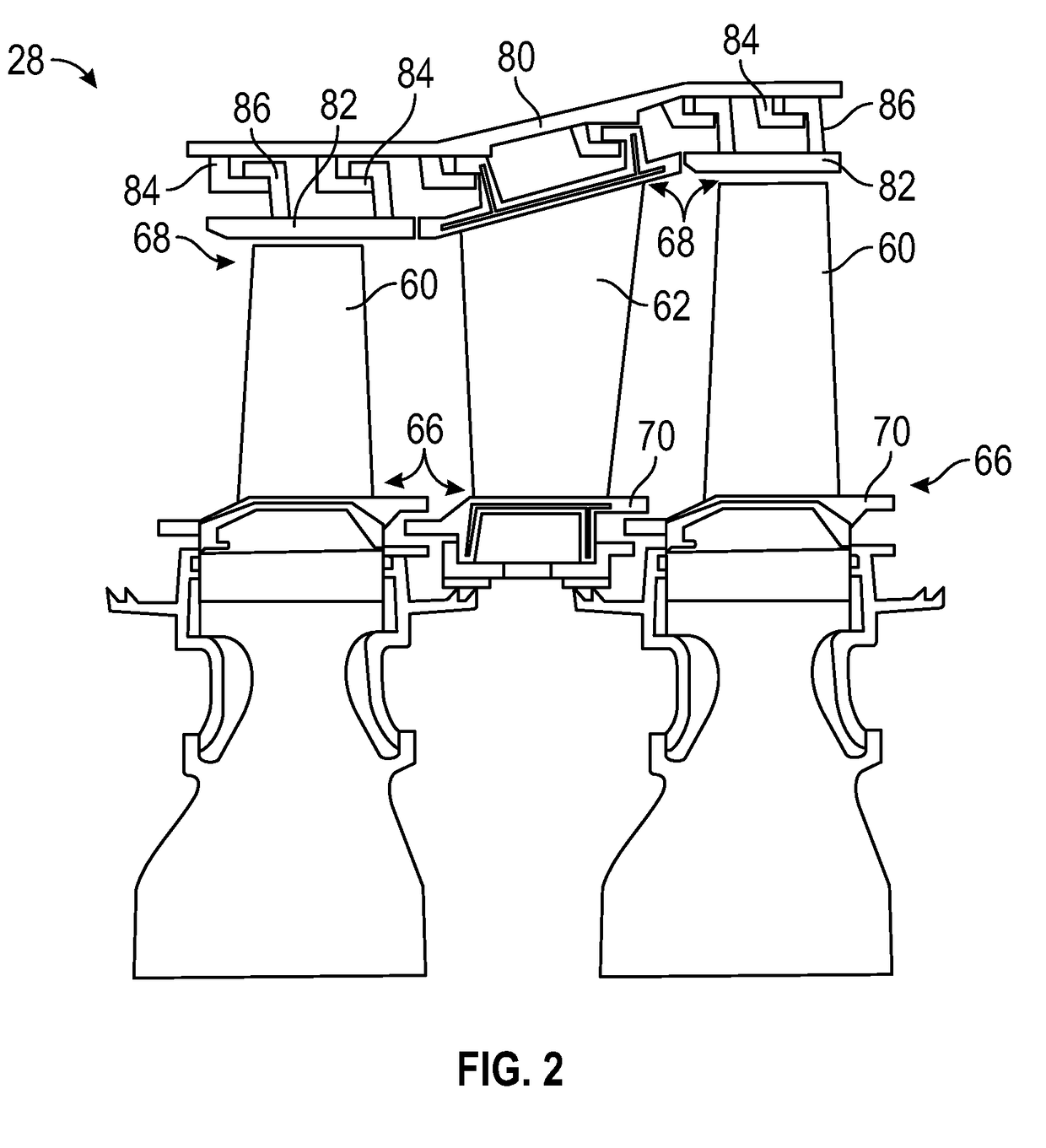
[0045]FIG. 1 schematically illustrates a gas turbine engine 20. The gas turbine engine 20 is disclosed herein as a two-spool turbofan that generally incorporates a fan section 22, a compressor section 24, a combustor section 26 and a turbine section 28. Alternative engines might include an augmentor section (not shown) among other systems or features. The fan section 22 drives air along a bypass flow path B in a bypass duct, while the compressor section 24 drives air along a core flow path C for compression and communication into the combustor section 26 then expansion through the turbine section 28. Although depicted as a two-spool turbofan gas turbine engine in the disclosed non-limiting embodiment, it should be understood that the concepts described herein are not limited to use with two-spool...


PUM

PropertyMeasurementUnit
Pressureaaaaaaaaaa
Dimensionaaaaaaaaaa
Heightaaaaaaaaaa

Abstract

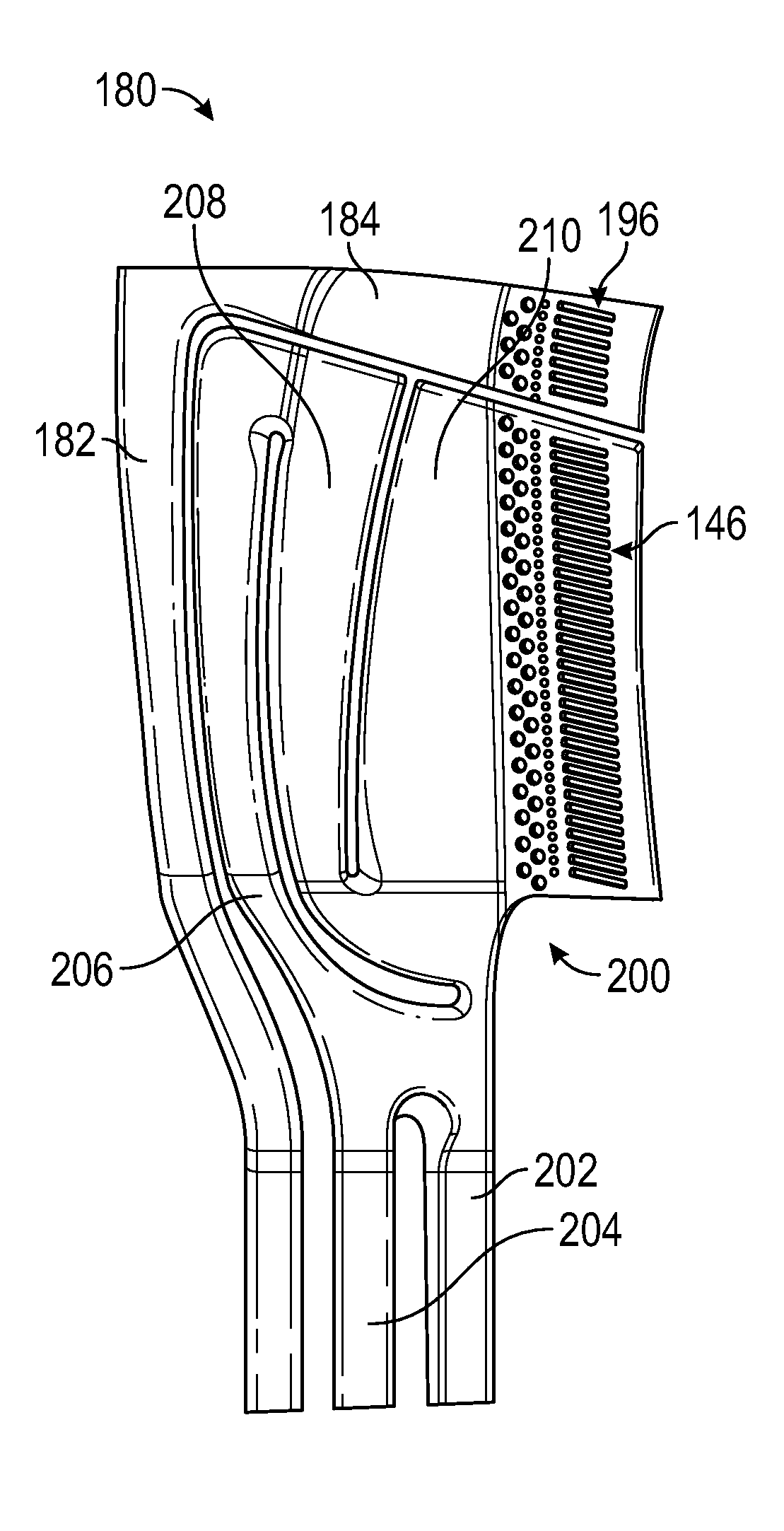
Core assemblies for manufacturing airfoils and airfoils made therefrom having an aft flowing serpentine hybrid skin core positioned relative to a plurality of core bodies and configured to define at least one serpentine cavity within the manufactured airfoil. The aft flowing serpentine hybrid skin core extends from a root region toward a tip region in a radial direction of the manufactured airfoil and the plurality of core bodies are positioned about the aft flowing serpentine hybrid skin core to form a shielding structure to thermally shield the aft flowing serpentine hybrid skin core in the manufactured airfoil.

Description

BACKGROUND[0001]Illustrative embodiments pertain to the art of turbomachinery, and specifically to turbine rotor components.[0002]Gas turbine engines are rotary-type combustion turbine engines built around a power core made up of a compressor, combustor and turbine, arranged in flow series with an upstream inlet and downstream exhaust. The compressor compresses air from the inlet, which is mixed with fuel in the combustor and ignited to generate hot combustion gas. The turbine extracts energy from the expanding combustion gas, and drives the compressor via a common shaft. Energy is delivered in the form of rotational energy in the shaft, reactive thrust from the exhaust, or both.[0003]The individual compressor and turbine sections in each spool are subdivided into a number of stages, which are formed of alternating rows of rotor blade and stator vane airfoils. The airfoils are shaped to turn, accelerate and compress the working fluid flow, or to generate lift for conversion to rotat...

Claims


Application Information

Patent Timeline
IPC IPC(8): F01D5/18F01D5/14
CPCF01D5/189F01D5/147F05D2300/5023F05D2300/21F05D2220/3215F01D5/187F01D5/20F05D2250/185Y02T50/60
Inventor CLUM, CAREYMONGILLO, JR., DOMINIC J.
Owner RAYTHEON TECH CORP
Learn More