System for monitoring crops and soil conditions

a technology for monitoring crops and soil conditions, applied in the field of measuring devices, can solve the problems of increasing the cost of cultivation,

Active Publication Date: 2018-06-07
AKER TECH
View PDF12 Cites 33 Cited by
  • Summary
  • Abstract
  • Description
  • Claims
  • Application Information

AI Technical Summary

Benefits of technology

[0011]According to yet another aspect, a method of monitoring crops and soil conditions includes operatively coupling a retractable boom assembly and elongate probe to an unmanned aerial system, retaining the retractable boom assembly and the elongate probe in a first position retracted proximal a body of the unmanned aerial system during launch, and extending the retractable boom assembly and the elongate probe to a second pos

Problems solved by technology

Each year, farmers incur substantial losses from weather, crop disease, pests, and poor field management.
Growing crops at large scale creates many challenges for growers, agricultural retailers and consultants, and agricultural pesticide distributors and manufacturers.
Current methods of crop health monitoring are manually intensive, time consuming, and prone to error.
However, it is difficult to properly monitor crops for insects, disease, plant nutritional deficiencies, and environmental effects due, in part, to the large size of individual fields, large scale of farm operations, and lack of available labor in the agricultural industry.
Physical crop scouting does not allow for timely or high resolution monitoring simply because a human cannot efficiently cover the extent of agricultural land.
Physical crop scouting may be challenging to accomplish due to the size and density of the crop (e.g. 10 foot tall corn) as well as environmental conditions such as water logged soils.
Human laborers are relatively less productive in harsh climates due to heat, humidity, and other weather conditions.
Therefore, the farmer may miss early warning indications of crop loss or yield limiting factors.
Similarly, remote sensing methods have associated difficulties.
While remote sensing m

Method used


Image

  • System for monitoring crops and soil conditions
  • System for monitoring crops and soil conditions
  • System for monitoring crops and soil conditions

Examples


Embodiment Construction

[0046]The detailed description set forth below is intended as a description of various implementations and is not intended to represent the only implementations in which the subject technology may be practiced. As those skilled in the art would realize, the described implementations may be modified in various different ways, all without departing from the scope of the present disclosure. Accordingly, the drawings and description are to be regarded as illustrative in nature and not restrictive. Throughout this disclosure, the terms “farmer” and “grower” have the same general meaning and are used interchangeably. Similarly, the terms “crop(s)” and “plant(s)” have the same general meaning and are used interchangeably herein.

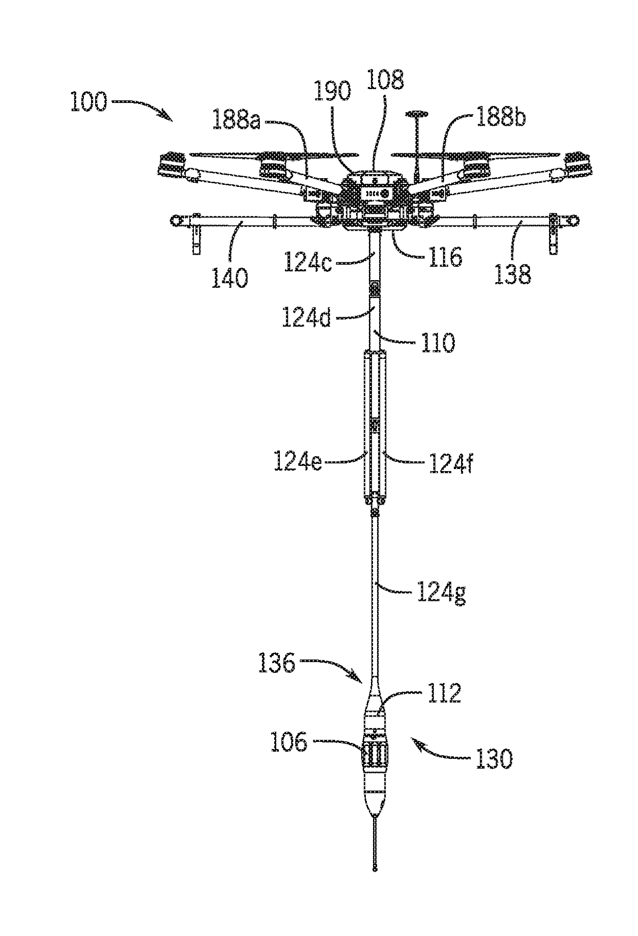
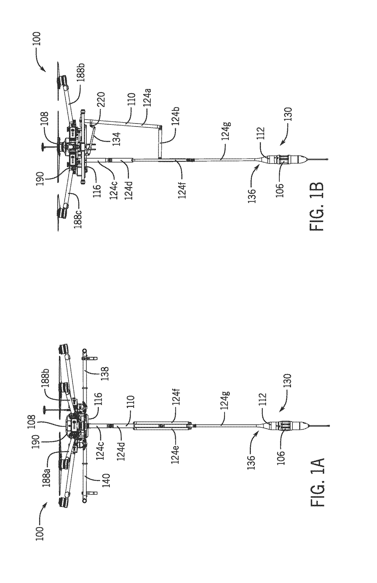
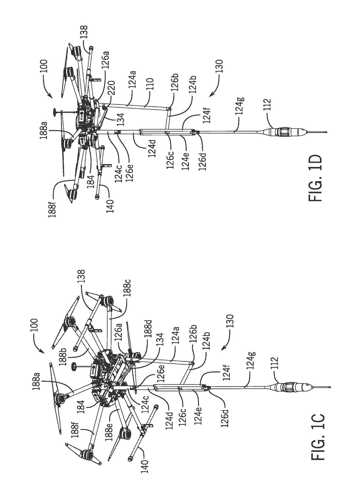
[0047]Referring to FIGS. 1 and 2, a system 100 disclosed herein allows for crop monitoring within a canopy 102 wherein the canopy 102 is the aboveground portion of one or more plant(s) or a crop 104, formed by the collection of individual plant crowns. The system 10...


PUM


Abstract

According to an aspect, a system for monitoring crops and soil conditions below a crop canopy includes a retractable boom assembly adapted to be coupled to an unmanned aerial vehicle. Further according to this aspect, the boom assembly includes an actuator and an elongate probe is coupled to the retractable boom assembly. Still further, the system includes a controller for maneuvering the elongate probe below the crop canopy while the boom assembly is extended by the actuator.

Description

CROSS REFERENCE TO RELATED APPLICATIONS[0001]The present application claims the benefit of U.S. provisional patent application No. 62 / 407,299, filed Oct. 12, 2016, entitled “Unmanned Aerial Drone Information Collection System”, and further claims the benefit of U.S. provisional patent application No. 62 / 442,158, filed Jan. 4, 2017, entitled “Unmanned Aerial Drone Information Collection System”, and further claims the benefit of U.S. provisional patent application No. 62 / 548,908, filed Aug. 22, 2017, entitled “System for Real-Time Assessment of Crop, Plant, and Field Conditions”, all owned by the assignee of the present application and the disclosures of which are hereby incorporated by reference herein.TECHNICAL FIELD[0002]The present description relates in general to measurement devices, and more particularly to a probe-based system for monitoring of crop, plant and field conditions.BACKGROUND OF THE DISCLOSURE[0003]Each year, farmers incur substantial losses from weather, crop dis...

Claims


Application Information

Patent Timeline
IPC IPC(8): G01N33/24G01N33/00B64C39/02A01B79/00
CPCG01N33/24G01N33/0098B64C39/024A01B79/005G01N2033/245B64C2201/108B64C2201/123B64C2201/145B64C2201/127B64U2101/00B64C39/02B64D47/00G01N33/02B64U30/20B64U2101/30B64U2201/104
Inventor SAEZ, ORLANDOGOLLY, TIMGOLLY, TODD
Owner AKER TECH
Why Eureka
Try Eureka