Charging cabinet

a charging cabinet and charging port technology, applied in the direction of electrical apparatus casings/cabinets/drawers, electrical apparatus connection, casings/cabinets/drawers details, etc., can solve the problems of not easy for users to find charging sockets, consume more power, and exhaust battery power of electronic products, so as to reduce the working hour and cost of charging electronic devices individually, improve the efficiency of charging operation, and improve the effect of convenience in us

Inactive Publication Date: 2018-06-21
CHEN-SOURCE INC
View PDF8 Cites 5 Cited by
  • Summary
  • Abstract
  • Description
  • Claims
  • Application Information

AI Technical Summary

Benefits of technology

[0007]A primary objective of the present disclosure is that a frame of a main body of the charging cabinet has a receiving space to place at least one electronic device, so that it is easier for the user to properly arrange the entire space configuration for the electronic device and to centralize management of the electronic device, and at least one electronic device can be electrically inserted in the at least one socket or adaptor socket disposed on a support plate of the frame, so that a power input module of the power supply device can be connected with an external power source to charge at least one electronic device, whereby the user does not need to search other host or power source for charging. As a result,

Problems solved by technology

The powerful electronic product (such as smartphone, tablet computer, and notebook computer and so on) also consumes more power, so it is easy to exhaust battery power of the electronic product when the user keeps operating the electronic product during movement, and user has to find a socket to charge the battery of the electronic product for further operation.
However, away from home, for example, when the

Method used


Image

  • Charging cabinet
  • Charging cabinet
  • Charging cabinet

Examples


Embodiment Construction

[0017]The technical content of the present invention will become apparent by the detailed description of the following embodiments and the illustration of related drawings as follows.

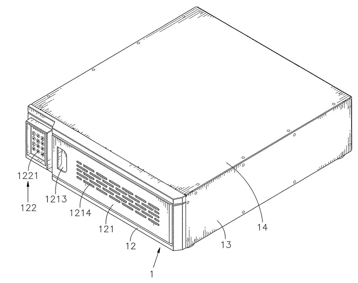
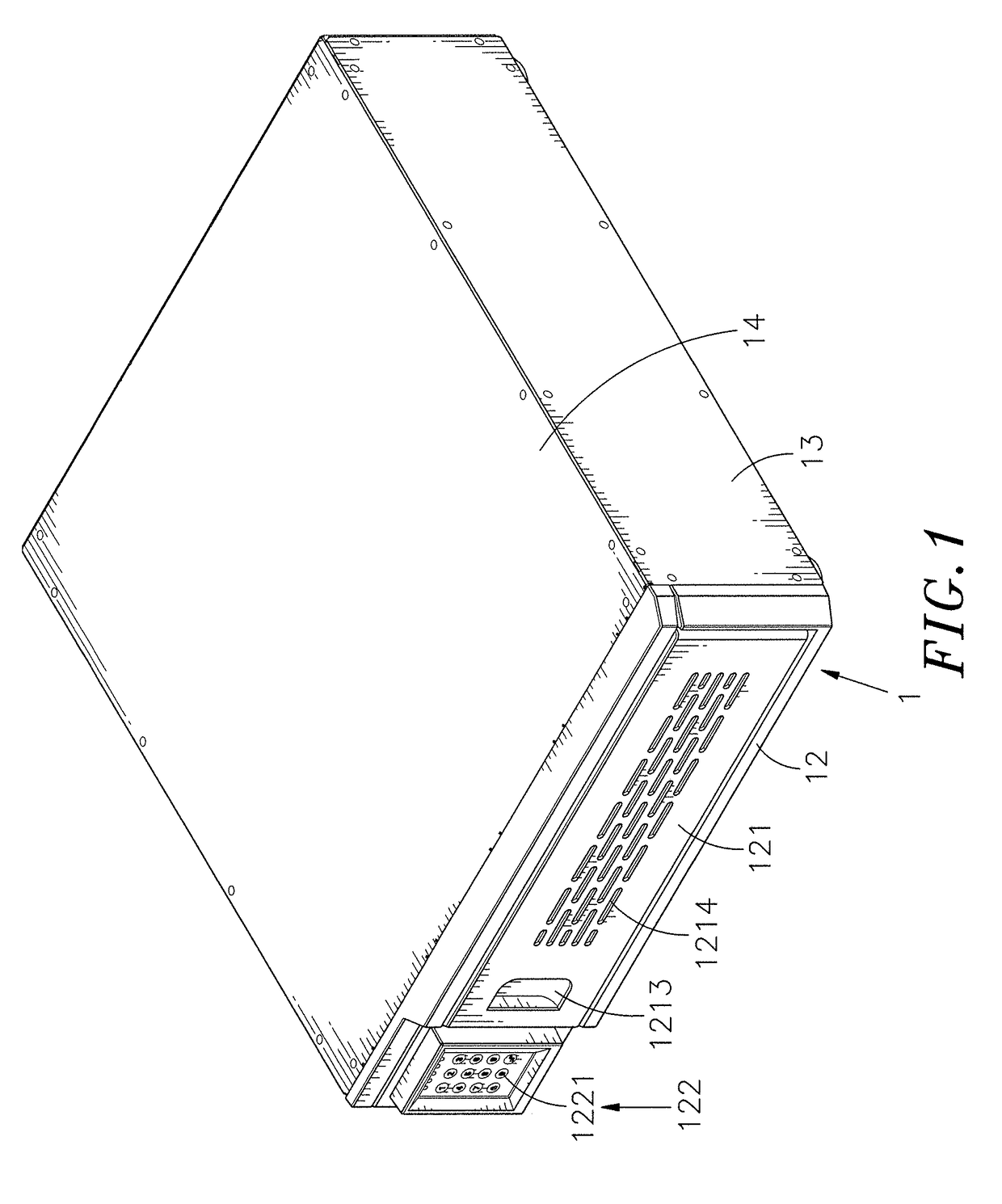
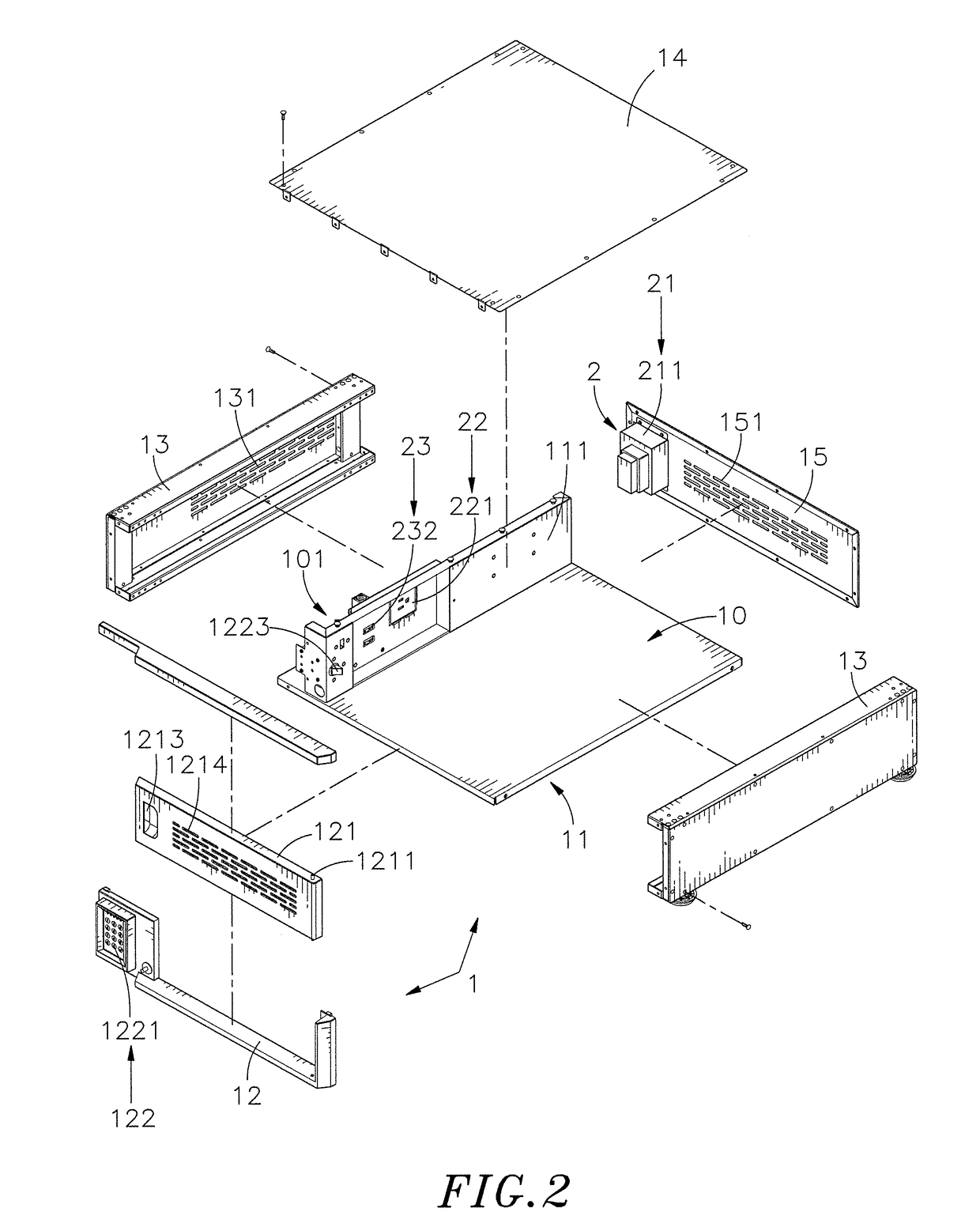
[0018]Please refer to FIGS. 1 through 3 which show an elevational view, an exploded view, and other exploded view when viewed from another angle, of a charging cabinet of the present disclosure. As shown in FIGS. 1 through 3, the charging cabinet of the present disclosure includes a main body 1 and a power supply device 2.

[0019]The main body 1 has a frame 11 which defines a hollow receiving space 10 therein, and at least one longitudinal support plate 111 is provided in the receiving space 10 to separate the receiving space 10 to form a stowing space 101 smaller than the receiving space 10. A panel 12 is disposed on a front surface of the frame 11, and a hinge lid 121 is movably disposed on the panel 12 corresponding in position to the receiving space 10. A locking device 122 is disposed at a side of th...


PUM


Abstract

The present disclosure illustrates a charging cabinet in which a main body comprises a frame defining a receiving space, a panel disposed on a front surface of the frame, a hinge lid movably disposed on the panel corresponding in position to the receiving space, a locking device disposed at a side of the hinge lid and configured to control open or lock of the hinge lid. The power supply device comprises a power input module connected with an external power source for supplying power to a power socket module and an expansion connection module which comprise a socket and an adaptor socket respectively. An electronic device can be placed into the receiving space to be charged through the power socket module or expansion connection module, and the hinge lid can be locked by the locking device, so as to achieve anti-theft effect.

Description

BACKGROUND OF THE INVENTION1. Field of the Invention[0001]The present disclosure relates to a charging cabinet, more particularly to a charging cabinet in which a main body includes a frame defining a receiving space inside, a panel located at the front of the frame, and a hinge lid pivotally connected to the panel corresponding in position to the receiving space. An electronic device can be placed into the receiving space to be charged through a power socket module or an expansion connection module of the power supply device, and the hinge lid can be locked by a locking device located at a side thereof, so as to achieve anti-theft effect.2. Description of the Related Art[0002]In recent years, electronic technology and multimedia information technology are rapidly developed, so electronic products (such as smartphone, tablet computer, notebook computer, and personal digital assistant and so on) become more powerful, but their sizes are developed to be more compact, lighter and small...

Claims


Application Information

Patent Timeline
IPC IPC(8): H02J7/00H01R31/06H05K5/03H05K5/02
CPCH02J7/0044H01R31/06H02J7/0052H02J2007/0059H05K5/0221H05K5/0226H05K5/0213H05K5/03H02J7/00
Inventor CHEN, YUN-HAO
Owner CHEN-SOURCE INC
Why Eureka
Try Eureka