Easy to Load Trimmer Head with Forced Discharge

a technology of forced discharge and trimmer head, which is applied in the direction of mowers, agricultural tools and machines, and mowers, etc., can solve the problems of commercially viable string trimmer with short mounting stems, limit the type of trimmer to which the trimmer head can attach, and reduce the cost of assembly

Active Publication Date: 2018-06-28
SHAKESPEARE CO
View PDF21 Cites 9 Cited by
  • Summary
  • Abstract
  • Description
  • Claims
  • Application Information

AI Technical Summary

Benefits of technology

[0030]In a fifteenth embodiment, the present invention provides a trimmer head as in either the first through fourteenth embodiments, wherein the spool further comprises at least three flanges essentially parallel to each other. The opposed ends of the passageway are located between the same two flanges, and wherein the same two flanges are operationally connected by at least one inclining portion on one of the two flanges and at least one opening on the other of the two flanges. This connection thereby allowing passage of the trimmer line up the at least one inclining portion, through the at least one opening, and into a space defined by the flange having the at least one opening and the third flange.

Problems solved by technology

If the line had been wound onto the spool in a second direction, then the line may release from the head or it may wind further onto the spool, possibly pulling completely into the trimmer head housing.
However, because the line channel goes through the middle of the head, this concept limits the type of trimmers to which the trimmer head can attach.
Basically, it is only commercially viable for a string trimmer with short mounting stems.
A significant issue in the design of Easy-Load Bump-Activated trimmer heads is that they are assembled from multiple molded parts.
Designing the assembly to operate without vibration is challenging.
And, there is also vibration contributed from the high speed rotation of the drive shaft, which connects the rotational power from the motor to the trimmer head.
As original equipment manufacturers (OEMs) of string trimmers try to adapt existing designs of trimmer heads to new electric trimmer designs, the contribution of vibration from trimmer heads is becoming more noticeable.
Some of the challenges of designing complex trimmer heads assembled from multiple molded parts are in designing the head to be free of vibration and to design the housing with minimal openings.
This later challenge is needed to prevent dirt and debris from enter the trimmer head, because dirt and debris will interfere with the performance and vibration properties of the trimmer head.
Preferably, new designs would not allow any dirt or debris to enter the assembled trimmer head.
The problem with these cylindrical shaped bump knobs is that they present a small surface area to the ground, and thus they tend to wear out quickly when used by commercial landscapers.
Additionally, the diameter of the cylindrical shape is typically less than 2 inches, and thus difficult to grip and turn; actions that are needed to turn the spool and thus wind trimmer line onto the easy-load bump heads.
However, these forces are less effective in pulling and extending the line from the head when less than 2 inches of line are extending from the head.

Method used


Image

  • Easy to Load Trimmer Head with Forced Discharge
  • Easy to Load Trimmer Head with Forced Discharge
  • Easy to Load Trimmer Head with Forced Discharge

Examples


Embodiment Construction

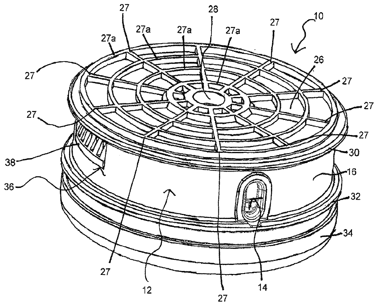
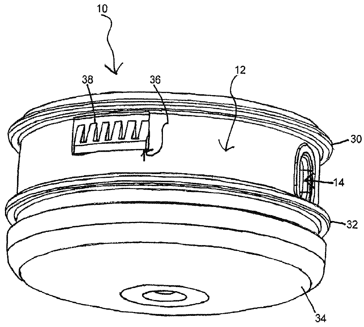
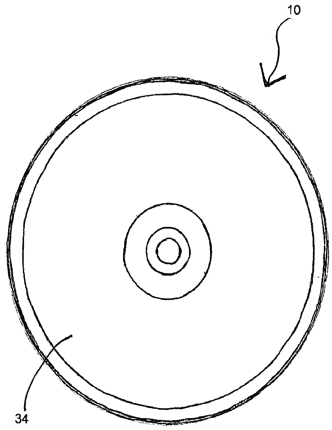
[0067]One representative embodiment of a trimmer head according to the concepts of the present invention is designated generally by the numeral 10 in FIGS. 1 to 4 herein. Details of this embodiment are depicted in FIGS. 1 through 19.

[0068]The trimmer head 10 is comprised of ten assembled pieces plus four screws. These components are combined into two main assemblies.

[0069]The first of these two assemblies is depicted in FIG. 6A. The assembly in FIG. 6A consists of the main housing 12, two eyelets 14, 14a pressed into openings on opposite sides of the sidewall 16 of the main housing 12, a metal shaft extension 18 and a biasing spring 20 which snaps around a post 22 located at the center of the housing 12. In an alternative embodiment, there are ramp projections 42 located immediately adjacent the post 22 and the biasing spring 20 snaps around the periphery of the ramp projections 42. The two eyelets 14, 14a are diametrically opposed and are shown to be oval or oblong in shape, but ma...


PUM


Abstract

A trimmer head for a trimmer having a shaft defining a rotation axis. The trimmer head comprising a housing including a main housing and a lower cover, and wherein the main housing contains a pair of opposed eyelets through which trimmer line is discharged. A spool encased within the housing, with a bump knob connected thereto, and having a passageway with opposed ends and extending from one side of the spool to another, the opposed ends being alignable with the eyelets to receive the line. A first set of a plurality of ramps located on an inside surface of the main housing and a second set of a plurality of ramps located within a center barrel of the spool. The two sets of ramps interact to control the direction of releasing line from the trimmer head and forcing indexing of the spool when the bump knob is bumped.

Description

CROSS REFERENCE TO RELATED APPLICATIONS[0001]This application claims the benefit of U.S. Provisional Patent Application No. 62 / 182,858 filed on Jun. 22, 2015, the disclosure of which is incorporated herein by reference.FIELD OF THE INVENTION[0002]This invention relates generally to line-type vegetation trimmer heads for rotary trimmers and, more specifically, to bump-activated trimmer heads for rotary trimmers using monofilament trimmer line as a means for cutting vegetation. More particularly, it relates to easy-load trimmer heads with a bump-activated indexing of trimmer line that operate with minimal vibration.BACKGROUND OF THE INVENTION[0003]There are a number of different classes of rotary trimmer heads, defined generally by the manner in which the trimmer line is fed, spooled or replaced in the trimmer head and / or by how the trimmer line is discharged, indexed or lengthened during use of the trimmer head.[0004]One such class of trimmer heads is the “bump-feed” or “bump-activat...

Claims


Application Information

Patent Timeline
Patent Type & Authority Applications(United States)
IPC IPC(8): A01D34/416
CPCA01D34/4166A01D34/4163A01G3/06
Inventor SKINNER, DAVID
Owner SHAKESPEARE CO
Why Eureka
Try Eureka