Jewelry bead and method of stringing same

a technology of beads and beads, applied in the field of beads, can solve the problems of affecting the ornamental appearance of the necklace, bracelet or the like, requiring the provision of methods for locking beads, and requiring stops, etc., and achieve the effect of easily hanging and permanently fixing

Inactive Publication Date: 2008-08-12
RONALD PRATT COMPANY
View PDF15 Cites 14 Cited by
  • Summary
  • Abstract
  • Description
  • Claims
  • Application Information

AI Technical Summary

Benefits of technology

[0009]Accordingly it is an object to the present invention to provide a necklace, bracelet, anklet or other beaded jewelry article whose beads can be strung easily on that article's chain or other support, yet can be permanently fixed easily at selected locations along that support.
[0015]As will be described in more detail later, each of the locking beads comprises a hollow shell having a pair of diametrically opposite holes therein through which the chain or other bead support may be threaded. The bead also has incorporated therein at the time of its manufacture a plastic tube which is aligned with the holes in the shell and compressed between the wall portions of the shell around those holes so that the tube remains aligned with the holes. Preferably, the inside diameter of the plastic tube is no smaller than the holes in the shell so that the bead support may be threaded easily through the holes in the bead when stringing the bead.

Problems solved by technology

In both cases, the stops, being located in the support outside the beads, may be visible and thus detract from the ornamental appearance of the necklace, bracelet or the like.
The conventional methods for locking beads are disadvantaged also in that the stops must be provided at the time the jewelry article is being assembled.
While that self locking bead performs its function quite well, it is disadvantaged somewhat in that it is difficult to initially string the beads along a chain or other support because the inner wall of the included plastic tube is smaller than the bead holes so that the tube frictionally engages the chain or other support during the stringing process.
In other words, the same feature which gives that prior bead its superior adjustable self locking function, also makes it more difficult to string that bead on its support in the first place.
Bearing in mind that a given necklace may have a large number of my prior beads, the process of stringing a necklace with those beads can be a tedious and time consuming task.

Method used


Image

  • Jewelry bead and method of stringing same
  • Jewelry bead and method of stringing same
  • Jewelry bead and method of stringing same

Examples


Embodiment Construction

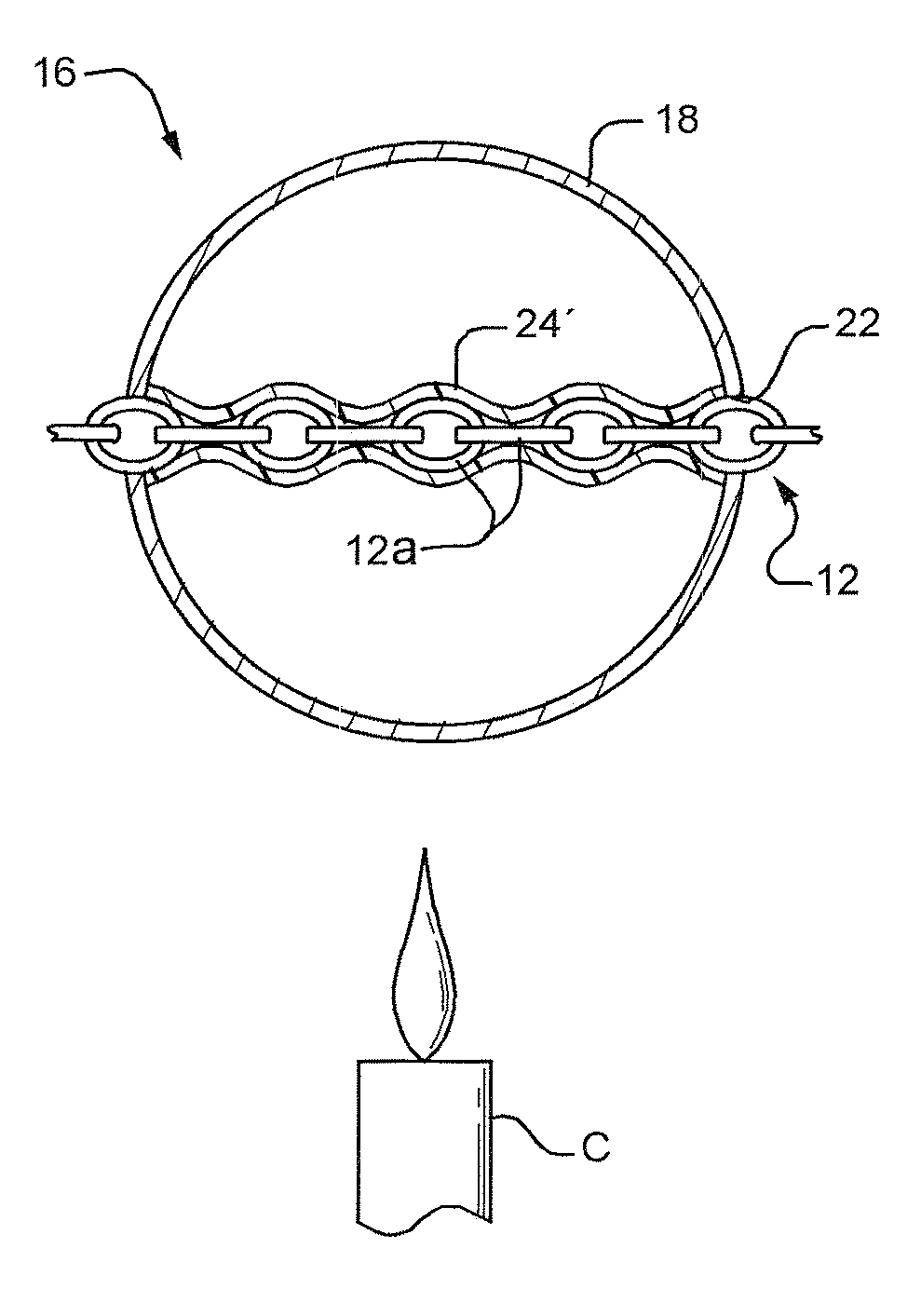
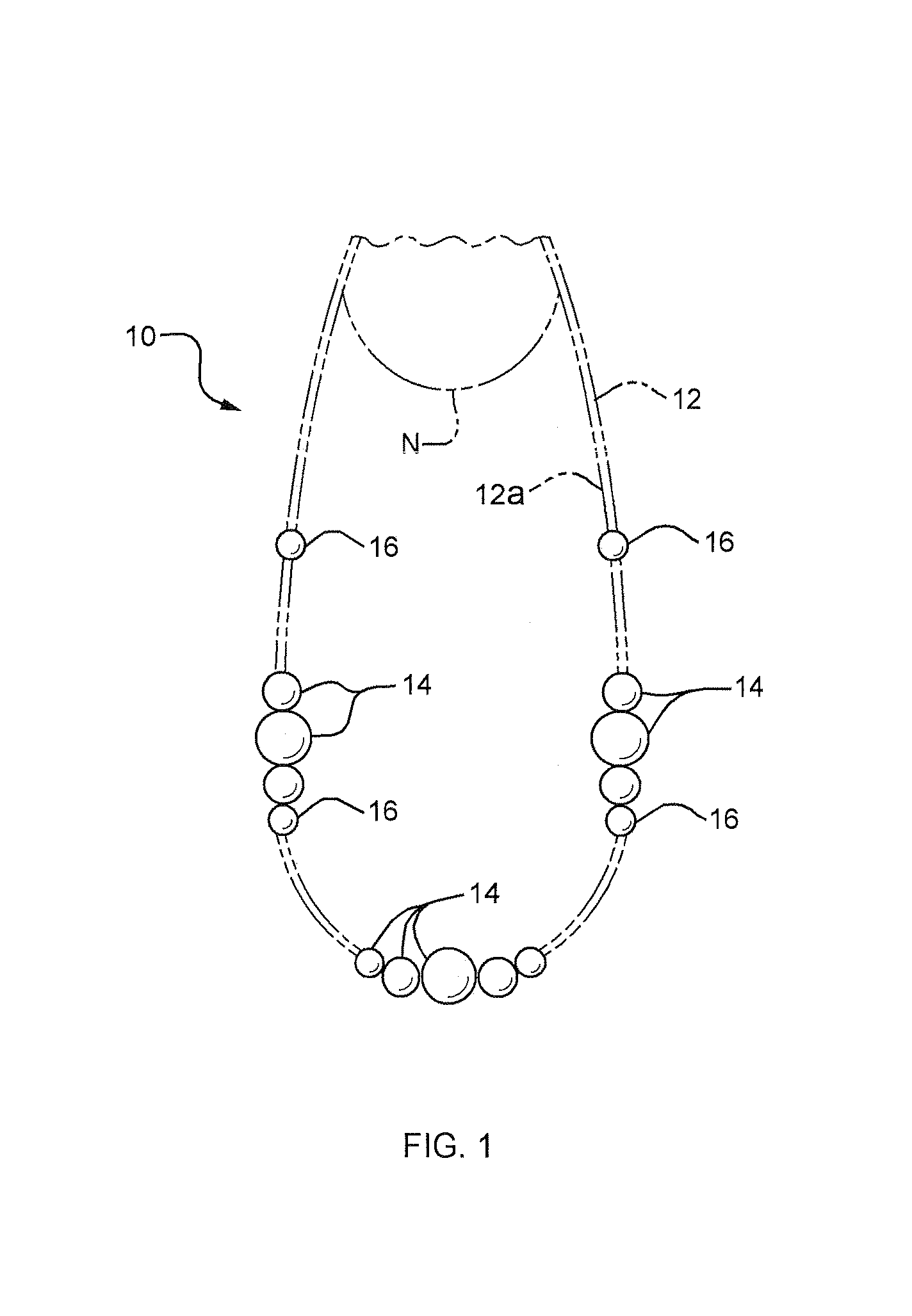
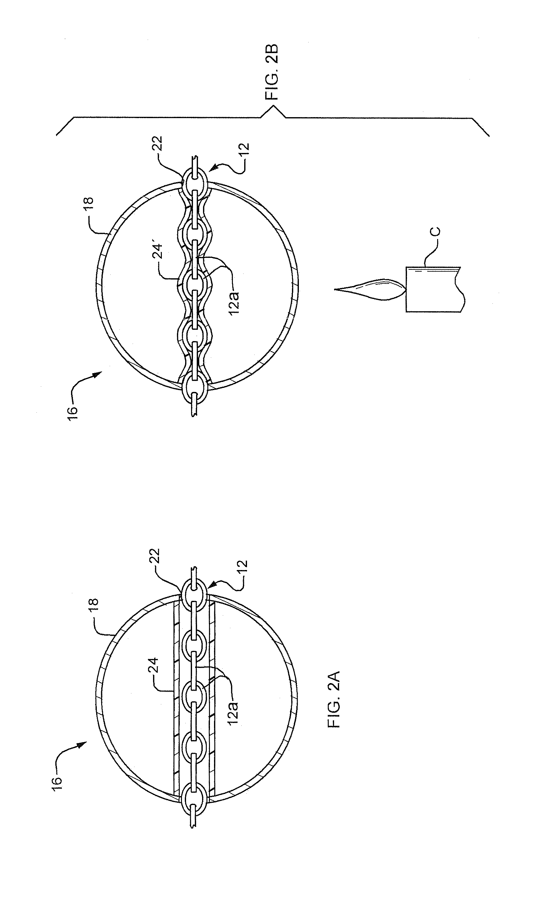
[0023]Referring to FIG. 1 of the drawing, a necklace 10 incorporating the invention is shown hung around a wearer's neck N. The illustrated necklace includes a bead support 12 in the form of a chain composed of interlocking links 12a which may be of any metal or other material suitable for making jewelry. Of course, other bead supports are possible including strings, wires, tubes, etc. The illustrated necklace 10 has beads 14 and a plurality of special locking beads 16. The various beads 14 are arranged in groups with those groups being maintained at selected positions along support 12 by the locking beads 16 which may be permanently fixed to the support. Of course, in another necklace, all of the beads on support 12 may be locking beads 16 spaced apart along the support.

[0024]While necklace 10 has only one ornamental strand, it is obvious that the invention can be incorporated into a multiple strand necklace, bracelet, anklet, etc. which would allow a variety of different bead spac...


PUM

PropertyMeasurementUnit
timeaaaaaaaaaa
inner diameteraaaaaaaaaa
diameteraaaaaaaaaa

Abstract

A jewelry article includes an elongated support and a multiplicity of beads strung along the support. At least one of the beads constitutes a locking bead consisting of a substantially closed hollow shell with a pair of aligned holes sized to slideably receive the support. A heat-shrinkable plastic tube is positioned inside the shell with its opposite ends captured by portions of said shell around the holes. The tube has a heat-deformed inner wall which substantially conforms to the support so as to permanently anchor the bead to the support. A method of stringing the locking bead is also disclosed.

Description

RELATED APPLICATION[0001]This application is a continuation of Ser. No. 11 / 076,594, filed Mar. 10, 2005, now abandoned.BACKGROUND OF THE INVENTION[0002]1. Field of the Invention[0003]This invention relates to jewelry. It relates more particularly to such jewelry consisting of hollow beads and similar ornaments strung on a support such as a chain or wire which can be engaged around a person's neck, wrist or ankle. In some cases the beads are spaced apart along the support; in other cases, they are arranged in groups which groups are spaced apart along the support. In either event, steps must be taken to provide stops for at least some of the beads to maintain the proper spacing of the individual beads or groups of beads along the support and to prevent them from sliding off the support in the event the support should break.[0004]2. Description of the Prior Art[0005]In conventional necklaces, bracelets, and the like the positions of some or all of the beads on the support are fixed by...

Claims


Application Information

Patent Timeline
Patent Type & Authority Patents(United States)
IPC IPC(8): A44C25/00A44C27/00A44C5/00
CPCA44C11/002Y10T29/4959Y10T29/49865Y10T29/49588
Inventor PRATT, RONALD
Owner RONALD PRATT COMPANY
Why Eureka
Try Eureka