Vacuum Cleaning Tool, Especially Hand-Held Nozzle, for a Vacuum Cleaner

a vacuum cleaner and hand-held technology, applied in the field of vacuum cleaners, can solve the problems that the alignment error of the holder provided in the housing of the support shaft does not affect the support action of the turbine, and achieve the effect of minimal power loss and minimal fluctuation of the power of the turbin

Inactive Publication Date: 2006-08-17
DUPRO AG
View PDF17 Cites 14 Cited by
  • Summary
  • Abstract
  • Description
  • Claims
  • Application Information

AI Technical Summary

Benefits of technology

[0004] It is an object of the present invention to provide a vacuum cleaning tool with a brush roller whose driving air turbine has a support that has only minimal power loss and, within a line of products, ensures minimal fluctuation of turbine power.
[0010] The bushing of the air turbine can extend through the sidewalls of the turbine channel and is axially supported outside of the turbine channel in bearings fixedly attached to the housing. In this way, axial oscillation of the air turbine is prevented.
[0012] Between the first and second sections there is expediently a circumferentially extending shoulder that forms a stop for the insertion depth of connecting tubes with greater outer diameter. For facilitating threading of a connecting tube and for broadening the diameter range of connectable tubes, it is provided that the inner diameter of one section widens in the flow direction of the vacuum air flow.
[0013] By arranging several vacuum air ports, of which at least one extends from the bottom of the working chamber into the front end face of the housing, a large mechanical action area for the brush roller is provided locally without the upholstery or the like to be cleaned penetrating too deep into the working chamber of the vacuum cleaning tool. The spatial configuration of the vacuum air ports enables excellent cleaning of corners, seams or the like. Since the partial vacuum air flows entering through the vacuum air ports, respectively, are combined in the working chamber and pass through the turbine chamber as a common vacuum air flow and drive the air turbine, a high torque and thus an excellent mechanical cleaning action are obtained.
[0015] When a vacuum air port extends from the bottom of the working chamber into the front end face of the housing, a configuration results that enables also excellent cleaning of corners, seams or the like. The vacuum air port extends across the housing edge formed by the bottom of the working chamber and the end face of the housing upwardly from the bottom into the end face of the housing.
[0017] By means of an advantageous spatial arrangement of the discharge opening, the turbine, and the brush roller in such a way that the center point of the discharge opening into the connecting socket, the air turbine axis, and the axis of rotation of the brush roller are positioned approximately in a common plane, a vacuum cleaning tool is provided that is easy to handle and has a great performance.

Problems solved by technology

In particular, alignment errors of the holder provided in the housing for the support shaft have no effect on the support action of the turbine.

Method used


Image

  • Vacuum Cleaning Tool, Especially Hand-Held Nozzle, for a Vacuum Cleaner
  • Vacuum Cleaning Tool, Especially Hand-Held Nozzle, for a Vacuum Cleaner
  • Vacuum Cleaning Tool, Especially Hand-Held Nozzle, for a Vacuum Cleaner

Examples


Embodiment Construction

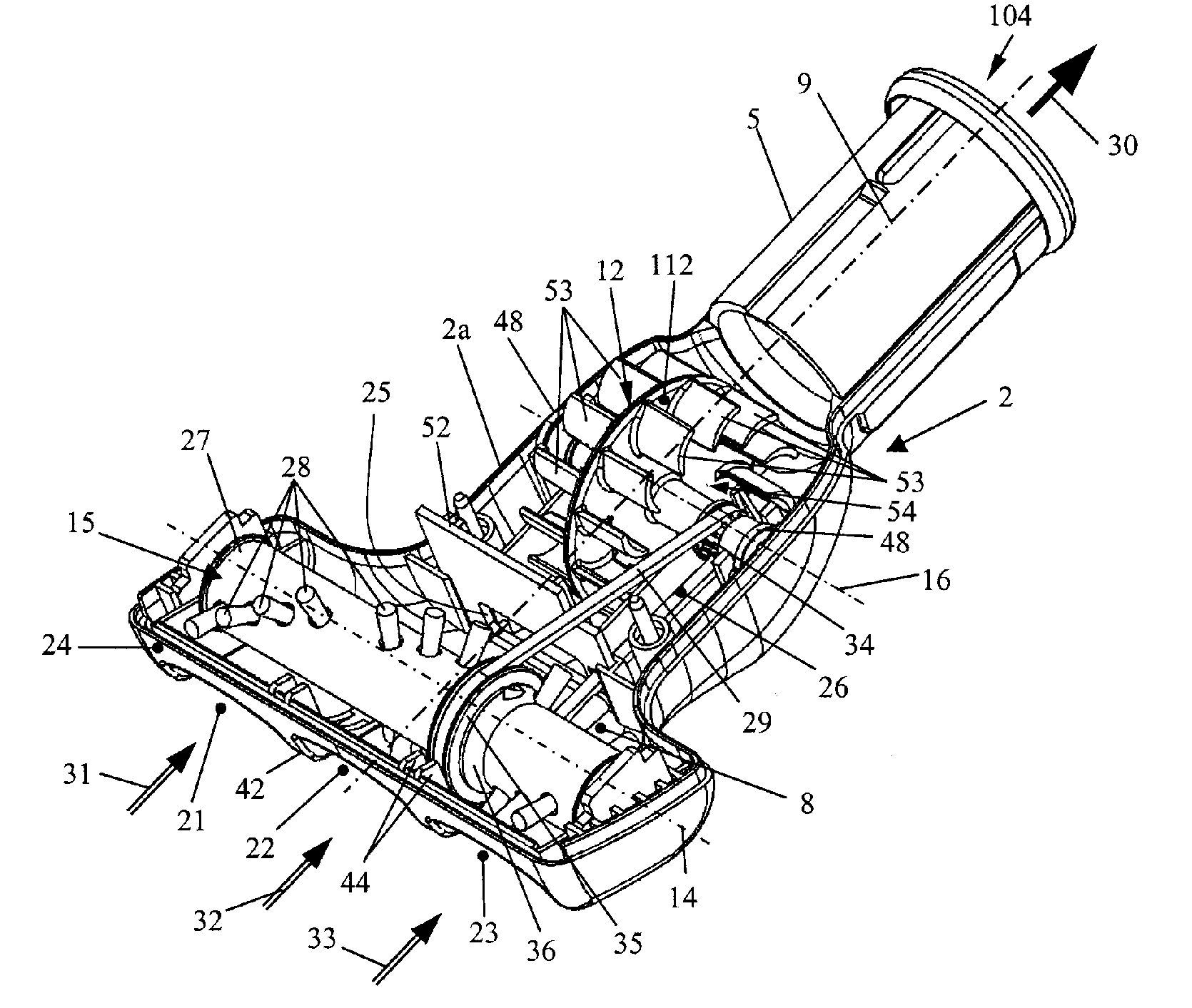
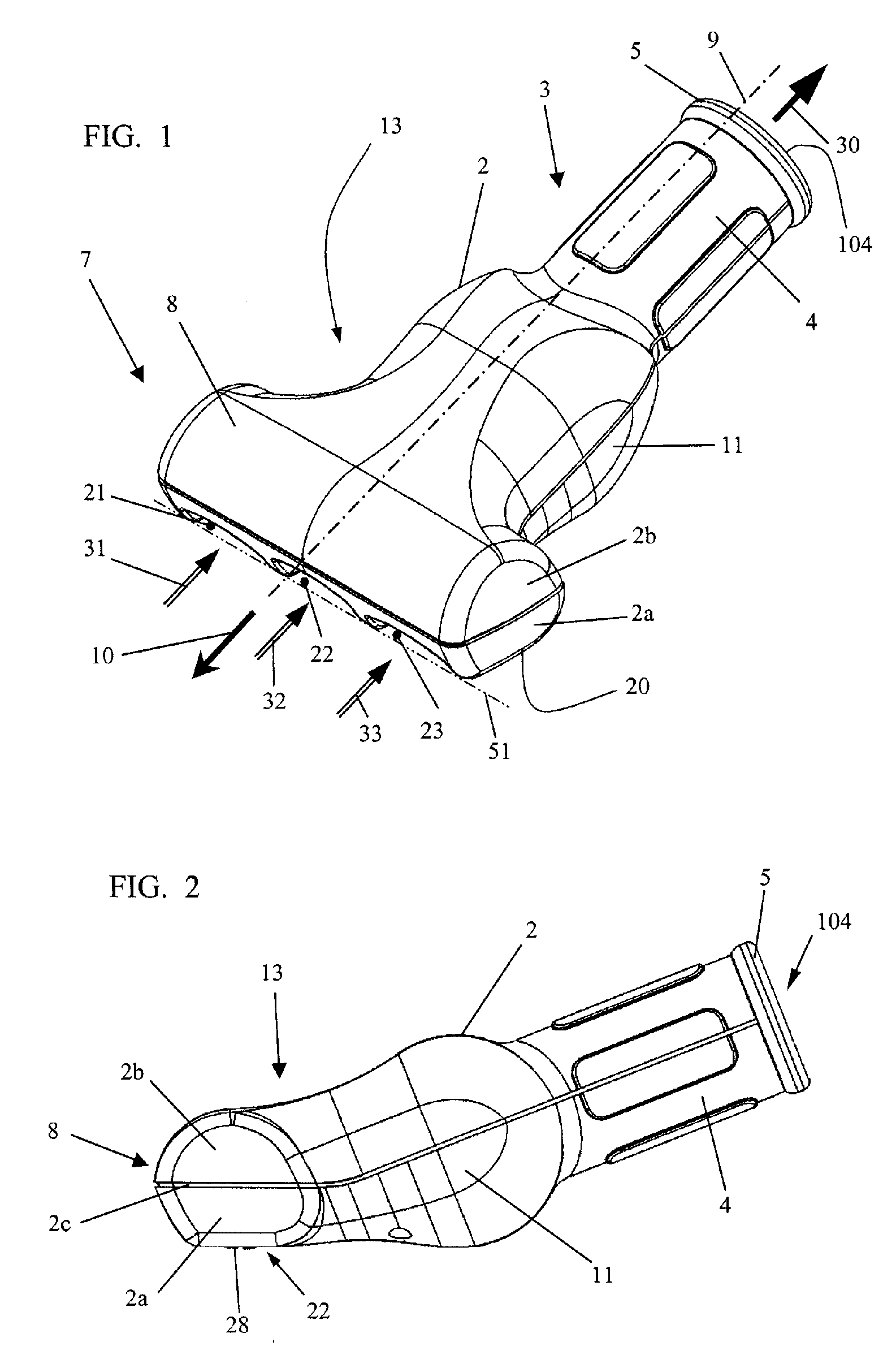
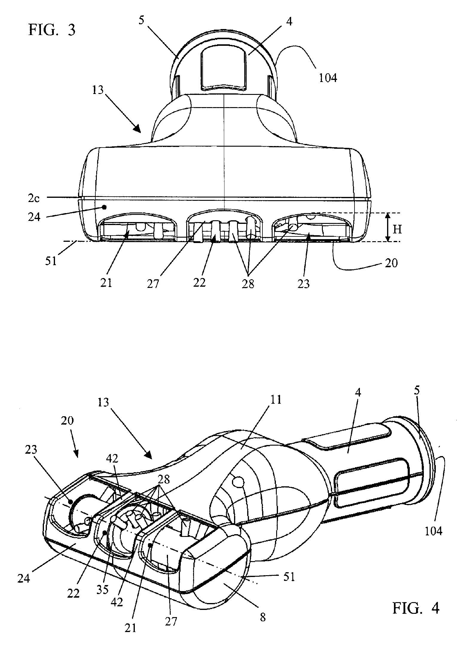
[0031] The vacuum cleaning tool 1 according to the invention illustrated in the Figures is provided to be connected to a vacuum hose of a vacuum cleaning device, not illustrated, particularly a vacuum cleaner. For this purpose, the housing 2 assembled from a housing top part 2b and a housing bottom part 2a is provided at its rearward end 3 with a connecting socket 4 that is formed as a unitary or monolithic part of the housing 2. As can be seen in particular in the section illustrations of FIG. 6 and FIG. 7, a socket insert 5 is inserted into the connecting socket 4 (see section illustration of FIG. 6); the socket insert 5 has a stepped inner diameter S1, S2 in order to receive in a vacuum-tight way connecting tubes of different diameters. For this purpose, the first section 71 formed at the open end 104 is provided with an inner diameter S1 that is greater than the inner diameter S2 of the inwardly positioned second section 72 that neighbors the turbine chamber 11. Preferably, the ...


PUM


Abstract

A vacuum cleaning tool has a housing with a working chamber and a connecting socket for a vacuum hose. A brush roller is arranged in the working chamber. An air turbine is arranged in a turbine chamber between working chamber and connecting socket. The working chamber has a bottom with vacuum air ports through which a vacuum air flow enters the working chamber. The housing has an opening between working chamber and turbine chamber and a discharge opening between turbine chamber and connecting socket. The vacuum air flow passes from the working chamber into the turbine chamber and drives the air turbine and then passes through the discharge opening into the connecting socket. The brush roller acts through the vacuum air ports on a surface to be treated. A bushing on which the air turbine is fixedly mounted is rotatably supported on a support shaft mounted in the housing.

Description

BACKGROUND OF THE INVENTION [0001] The invention relates to a vacuum cleaning tool for a vacuum cleaning device, in particular, for a vacuum cleaner or the like, comprising a housing having at its front end a working chamber for a brush roller and at the opposed end a connecting socket for attaching a vacuum hose. Between the working chamber and the connecting socket a turbine chamber for an air turbine is arranged in the housing. The working chamber is essentially transversely arranged relative to the longitudinal axis of the vacuum cleaning tool. The bottom of the working chamber is provided with at least one vacuum air port through which a vacuum air flow enters the working chamber. A connecting opening between the working chamber and the turbine chamber is provided through which the vacuum air flow enters the turbine chamber and drives the air turbine. The vacuum air flow passes through the discharge opening into the connecting socket. The air turbine drives the brush roller in ...

Claims


Application Information

Patent Timeline
Patent Type & Authority Applications(United States)
IPC IPC(8): A47L5/26A47L5/10
CPCA47L9/0416
Inventor WORWAG, PETER
Owner DUPRO AG
Why Eureka
Try Eureka