Retrofitting a vehicle to transfer mechanical power out of an engine compartment

a technology for mechanical power and vehicles, applied in mechanical equipment, transportation and packaging, gearing, etc., can solve the problems of consuming much more power than can be delivered, components more costly to produce, and components attached within the engine compartment are difficult to maintain, so as to achieve minimal power loss, improve efficiency, and reduce the effect of siz

Inactive Publication Date: 2014-05-13
AURA SYST INC
View PDF28 Cites 3 Cited by
  • Summary
  • Abstract
  • Description
  • Claims
  • Application Information

AI Technical Summary

Benefits of technology

[0007]The retrofitting entity retrofits the vehicle to include the MPTS and the electrical generator. The retrofitting entity installs the electrical generator to a portion of the chassis (or vehicle body) that is outside of the engine compartment. By installing the electrical generator outside the engine compartment, a larger and more powerful electrical generator can be realized. If the retrofitting entity were to install the electrical generator within the engine compartment, then the electrical generator selected would be smaller in size due to the tight space constraints within the engine compartment. Moreover, due to the harsh operating conditions within the engine compartment (such as high temperatures and extreme vibrations), installment of the electrical generator outside the engine compartment avoids these conditions that tend to wear and ultimately damage the generator.
[0008]The retrofitting entity utilizes the MPTS to transfer power out of the engine compartment to the electrical generator. The MPTS forms a mechanical linkage that includes a first coupling mechanism, a shaft, and a second coupling mechanism. The retrofitting entity couples the first coupling mechanism to the engine crankshaft and to a first end of the shaft, and couples the second coupling mechanism to the second end of the shaft and to the generator shaft. The mechanical linkage formed by the MPTS extends from the engine crankshaft, through the engine compartment, and onto the generator crankshaft. By installing the MPTS in this fashion, the MPTS effectively couples the engine crankshaft to the generator shaft. Additionally, the mechanical linkage does not include any Power Take-Off mechanism (such as a PTO unit or hydraulic pump) resulting in minimal power loss as compared to conventional power transfer techniques. Moreover, the mechanical linkage does not include a clutch system or disengagement mechanism, hence the mechanical linkage always remains engaged (unless the MPTS is uninstalled). As a result, the secondary power generation system generates power during engine idle when the engine crankshaft is rotating at a low RPM, and also generates power when the engine is operating normally and the engine crankshaft is rotating at a high RPM. Secondary power generation system tends to operate more efficiently and generates a greater amount of electrical energy than is generated using conventional power generation systems.

Problems solved by technology

Such components that are installed in engine compartment 13 must be rated for operating under these extreme conditions making such components more costly to produce.
Second, components attached within the engine compartment are difficult to maintain as compared to components residing outside of the engine compartment.
A significant problem arises if there are demanding power generation requirements where a large generator is required that does not fit within engine compartment 13.
The refrigeration system consumes much more power than can be delivered by the primary power generation system.
Moreover, due to the harsh operating conditions within the engine compartment (such as high temperatures and extreme vibrations), installment of the electrical generator outside the engine compartment avoids these conditions that tend to wear and ultimately damage the generator.

Method used


Image

  • Retrofitting a vehicle to transfer mechanical power out of an engine compartment
  • Retrofitting a vehicle to transfer mechanical power out of an engine compartment
  • Retrofitting a vehicle to transfer mechanical power out of an engine compartment

Examples


Embodiment Construction

[0046]Reference will now be made in detail to some embodiments of the invention, examples of which are illustrated in the accompanying drawings.

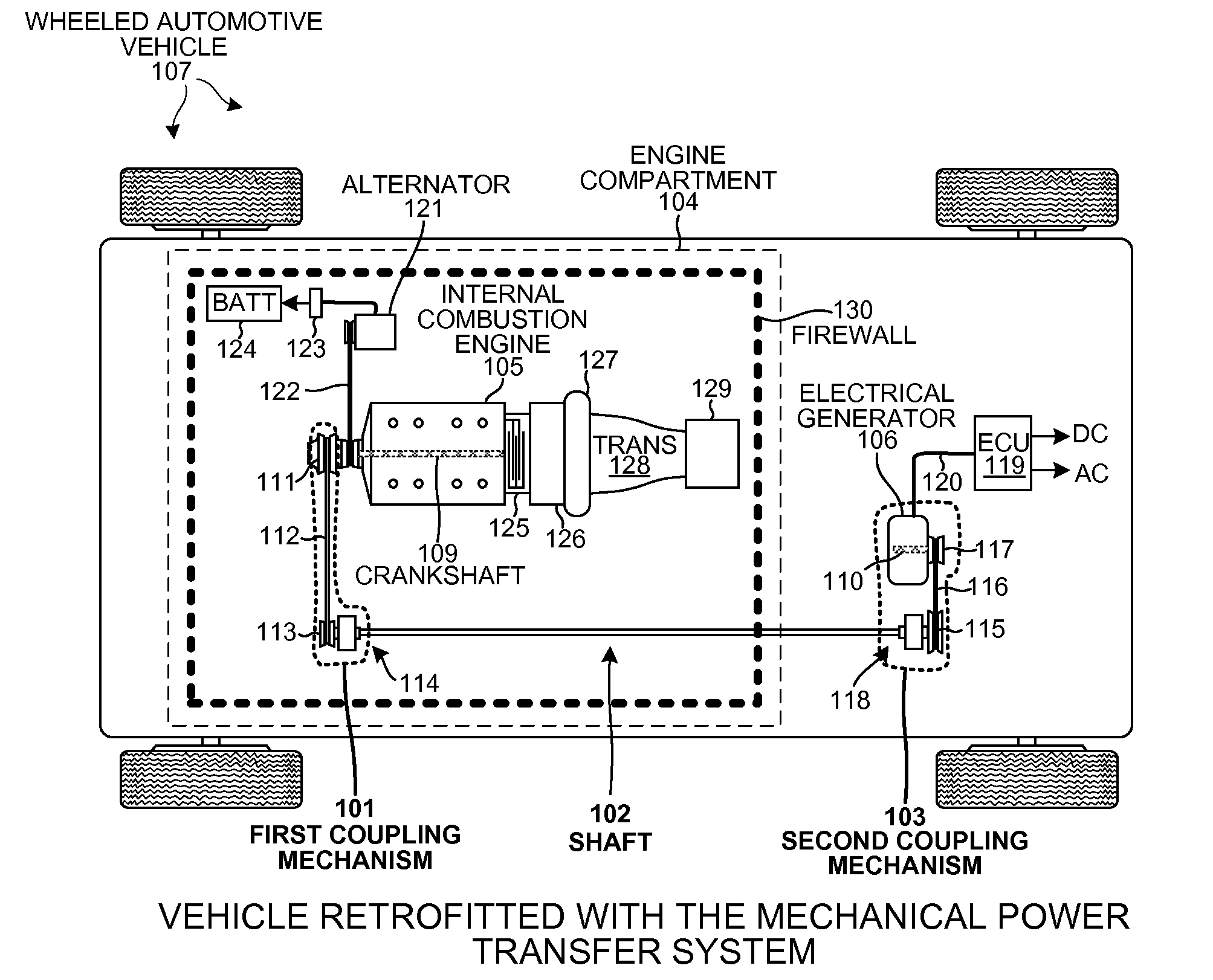
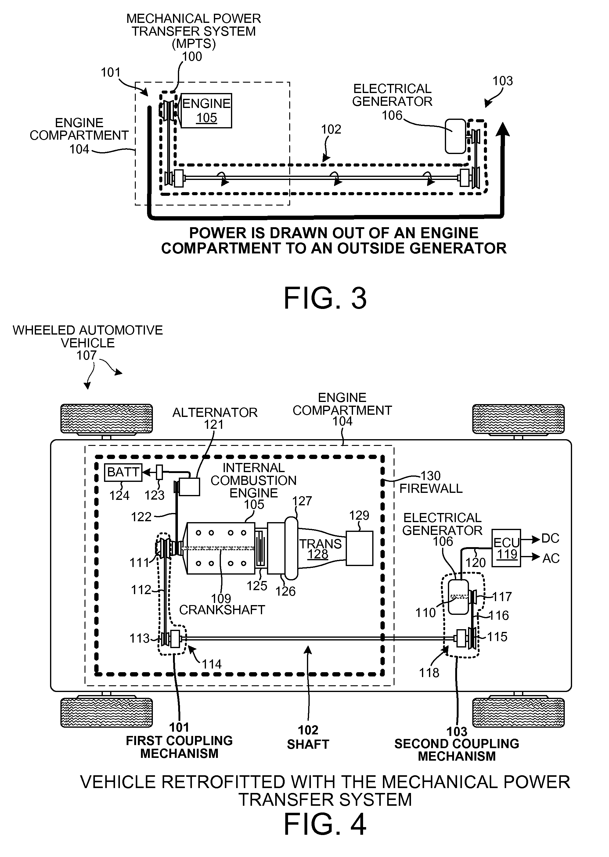
[0047]FIG. 3 is a diagram of a Mechanical Power Transfer System (MPTS) 100 that draws power out of an engine compartment, in accordance with one novel aspect. MPTS 100 comprises a first coupling mechanism 101, a shaft 102, and a second coupling mechanism 103. The first coupling mechanism 101 couples a crankshaft of internal combustion engine 105 to one end of shaft 102, and the second coupling mechanism 103 couples an opposite end of shaft 102 to a shaft of electrical generator 106. In this fashion, mechanical power is drawn out of engine compartment 104 and transferred to electrical generator 106 that is disposed outside of the engine compartment 104. Electrical generator 106 converts the torque output by the engine 105 into electrical power that is supplied and consumed by other components disposed outside of engine compartment 104.

[0048]F...


PUM


Abstract

A vehicle is retrofitted with a secondary power generation system having a Mechanical Power Transfer System (MPTS) and an electrical generator. The MPTS transfers power from an engine crankshaft within an engine compartment to a generator shaft of the electrical generator disposed outside of the engine compartment. Retrofitting the vehicle with the MPTS allows the electrical generator to be attached to a portion of a chassis of the vehicle that is outside of the engine compartment. Attachment of the electrical generator outside the engine compartment avoids the tight space constraints and harsh operating conditions (high operating temperatures) within the engine compartment. Thus a larger, more powerful generator that requires less maintenance is realized. Additionally, the MPTS does not include any Power Take-Off mechanism, clutch system, or disengagement mechanism resulting in more efficient power transfer and in an overall increase in the amount of electrical energy generated than in conventional techniques.

Description

CROSS REFERENCE TO RELATED APPLICATION[0001]This application claims the benefit under 35 U.S.C. §119 of provisional application Ser. No. 61 / 516,071, entitled “Mechanically Transferring Power From An Engine To A Generator Located Outside An Engine Compartment”, filed Mar. 28, 2011. The subject matter of provisional application Ser. No. 61 / 516,071 is incorporated herein by reference.TECHNICAL FIELD[0002]The described embodiments relate to drawing engine power out of an engine compartment.BACKGROUND INFORMATION[0003]Wheeled automotive vehicles typically include a primary power generation system that converts mechanical power drawn from an engine crankshaft into electrical energy. The electrical energy is then consumed by components present on the vehicle. In the example of FIG. 1 (Prior Art), a wheeled automotive vehicle 10 includes an engine 11 and an engine crankshaft 12 disposed within an engine compartment 13. Vehicle 10 includes a power generation system comprising alternator 14. ...

Claims


Application Information

Patent Timeline
Patent Type & Authority Patents(United States)
IPC IPC(8): B60K6/42
CPCF16H7/02B60K25/02B60Y2304/076
Inventor COHEN, YEDIDIA
Owner AURA SYST INC
Why Eureka
Try Eureka