Spacecraft momentum management using solar array

a solar array and spacecraft technology, applied in process and machine control, instruments, navigation instruments, etc., can solve the problems of shortening the maneuver life of the spacecraft and substantial power loss penalty of the spacecraft, and achieve the effect of minimal power loss due to solar array offs

Active Publication Date: 2014-10-21
MAXAR SPACE LLC
View PDF12 Cites 3 Cited by
  • Summary
  • Abstract
  • Description
  • Claims
  • Application Information

AI Technical Summary

Benefits of technology

[0009]The present inventors have recognized that a spacecraft momentum management system may advantageously use a variably commanded solar array offset to cause actually stored spacecraft momentum to closely track a target profile. In an embodiment, a requirement for thruster actuations to unload momentum is substantially eliminated, and a power loss due to solar array offset is minimal.
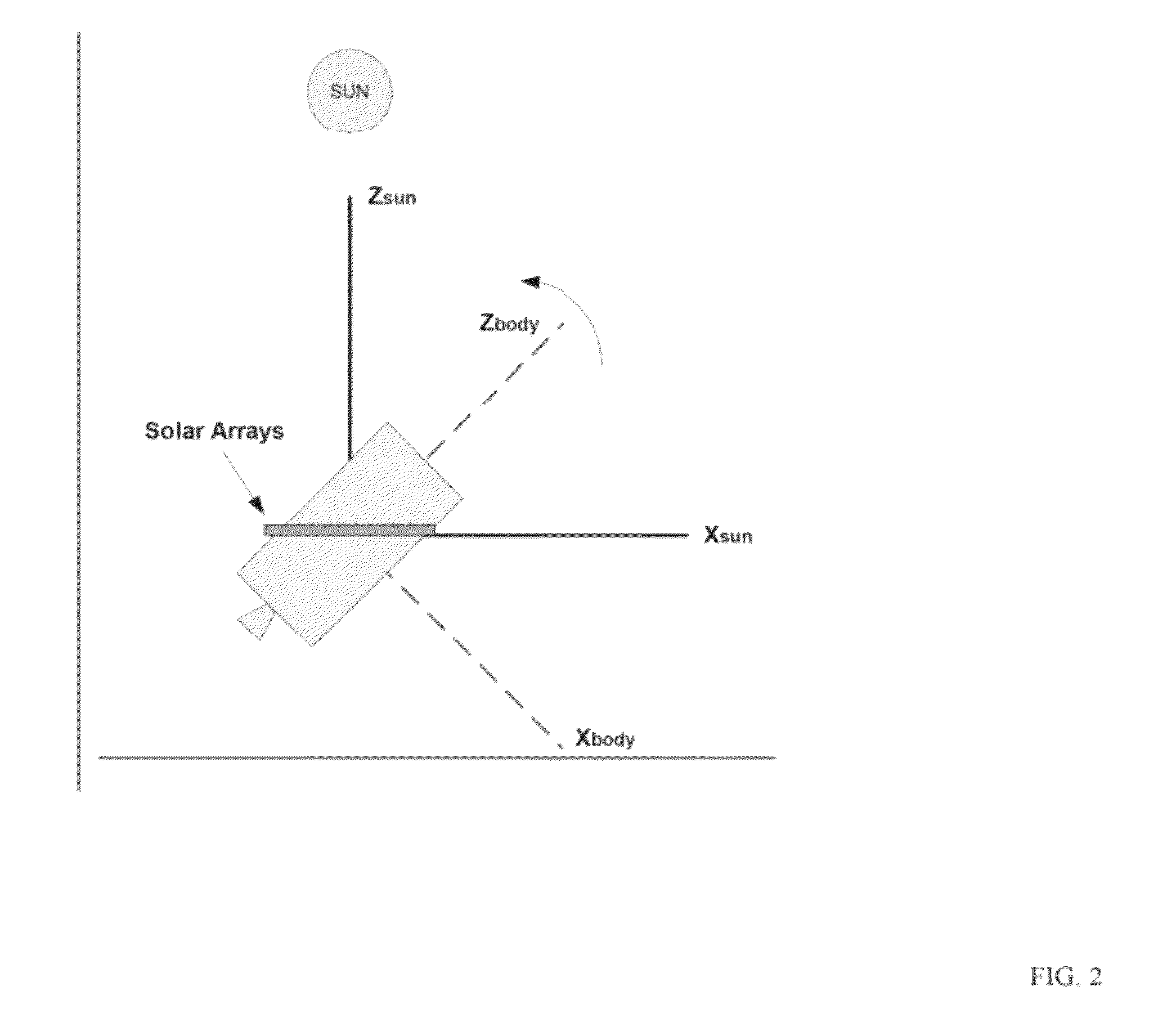
[0010]Advantageously, an estimate of the cyclical component of the stored spacecraft momentum target profile at a given instant may be subtracted from the actually stored spacecraft momentum to compute a momentum “error”. The momentum error may then be substantially eliminated by providing a variably commanded solar array offset. In an embodiment, only a non-cyclical component of spacecraft momentum is unloaded by the solar array offset. As a result of this technique, the inventors have found, the magnitude of the solar array offset may be minimized, and associated power losses made negligibly small. Moreover, an amount of actuation of a solar array drive assembly mechanism associated with momentum management is minimized. This not only minimizes power loss due to solar array offset, but also prevents over actuation of the mechanism.
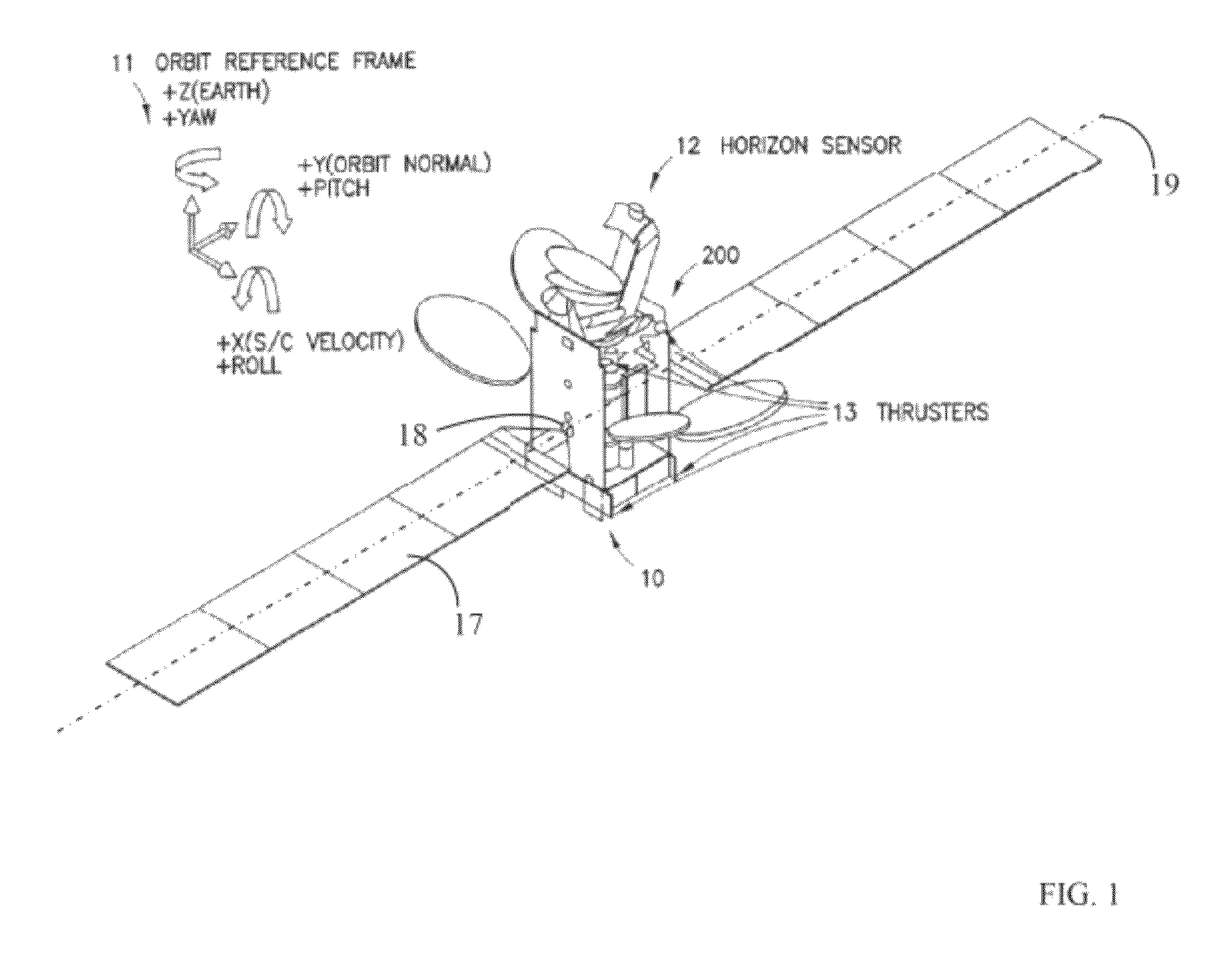
[0017]In an embodiment each of the target profile and the actually stored momentum value are determined separately with respect to each of a yaw axis and a roll axis of the spacecraft, and the produced torque is one of (i) a substantially pure inertial yaw torque, and (ii) a combined inertial roll / yaw torque. The produced torque may be the combined inertial roll / yaw torque selected from among (i) positive roll / positive yaw, (ii) positive roll / negative yaw, (iii) negative roll / positive yaw, and (iv) negative roll / negative yaw, such that the produced torque reduces at least one of a roll MSE and a yaw MSE. The produced torque may reduce both roll MSE and yaw MSE.
[0020]In another embodiment, the pitch MSE is reduced without recourse to the spacecraft propulsion system. The pitch MSE may be reduced by producing a pitch torque on the spacecraft, said pitch torque resulting from at least one of adjusting an angle of at least one solar array with respect to a pitch axis of the spacecraft and actuating a solar array trim tab.

Problems solved by technology

Solar sailing techniques generally require a significant array offset from solar normal, resulting in a substantial power loss penalty to the spacecraft.
Nevertheless, according to the disclosure of McGovern, momentum unloads using thrusters are required, resulting in a significant propellant expenditure, with a consequent shortening of spacecraft maneuver life.

Method used


Image

  • Spacecraft momentum management using solar array
  • Spacecraft momentum management using solar array
  • Spacecraft momentum management using solar array

Examples


Embodiment Construction

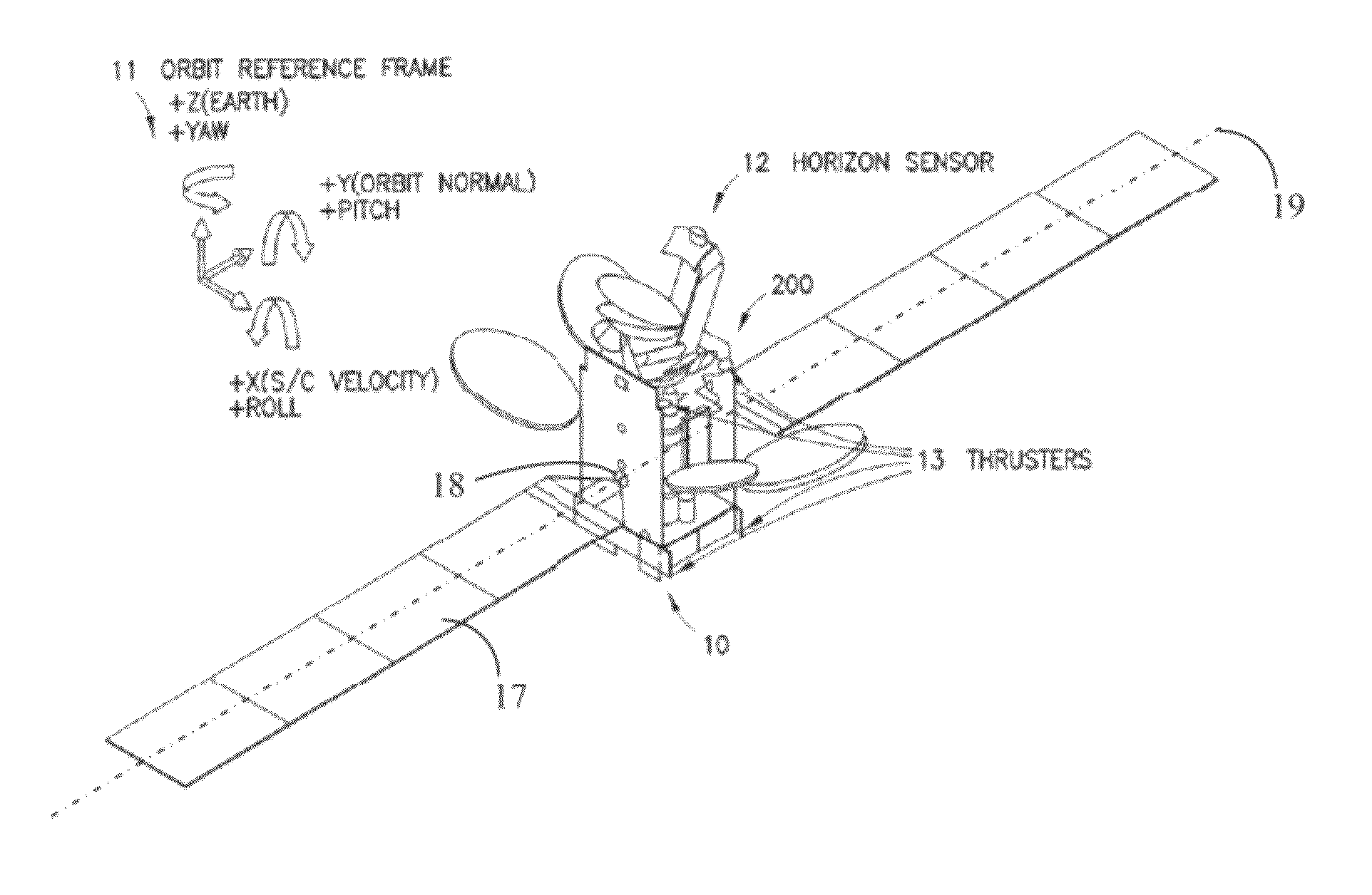
[0039]Specific exemplary embodiments of the invention will now be described with reference to the accompanying drawings. This invention may, however, be embodied in many different forms, and should not be construed as limited to the embodiments set forth herein. Rather, these embodiments are provided so that this disclosure will be thorough and complete, and will fully convey the scope of the invention to those skilled in the art.

[0040]It will be understood that when an element is referred to as being “connected” or “coupled” to another element, it can be directly connected or coupled to the other element, or intervening elements may be present. Furthermore, “connected” or “coupled” as used herein may include wirelessly connected or coupled. It will be understood that although the terms “first” and “second” are used herein to describe various elements, these elements should not be limited by these terms. These terms are used only to distinguish one element from another element. Thus...


PUM


Abstract

Stored momentum on a spacecraft is managed by determining a target profile of stored momentum as a function of time for the spacecraft; measuring a difference between a momentum value actually stored on the spacecraft and a desired momentum value, where the desired momentum value substantially conforms to the target profile at a particular time; reducing the difference by producing a torque on the spacecraft, where the torque results from selectively controlling at least one solar array position offset angle, the offset angle being an offset of at least one solar array of the spacecraft from a nominal sun pointing direction.

Description

TECHNICAL FIELD[0001]This invention relates generally to spacecraft attitude control systems and, in particular, to using a spacecraft solar array to manage spacecraft momentum.BACKGROUND[0002]The assignee of the present invention manufactures and deploys spacecraft for, inter alia, communications and broadcast services. The three axis orientation of these spacecraft with respect to celestial bodies such as the earth and sun must be controlled in a desired attitude within a narrow tolerance.[0003]An orbiting spacecraft is subjected to a disturbance torque environment sufficient to perturb the spacecraft from the desired attitude, at least in the absence of counteracting torques from a spacecraft attitude control system and / or propulsion system. A major component of the disturbance torque environment has a substantially periodic nature. For example, as disclosed in McGovern, et al., U.S. Pat. No. 6,672,544 (hereinafter, McGovern), assigned to the assignee of the present invention, an...

Claims


Application Information

Patent Timeline
Patent Type & Authority Patents(United States)
IPC IPC(8): B64G1/24G05D1/00G05D1/08
CPCG05D1/0883B64G1/365B64G1/405B64G1/24B64G1/283B64G1/407B64G1/44B64G1/361B64G1/26B64G1/244
Inventor MUNIR, MOHAMMAD SAGHIRCOOPER, JOHN HUTTONHIRSCHBERG, PHILIP CONWAY
Owner MAXAR SPACE LLC
Why Eureka
Try Eureka