Power combiner/divider using mutual inductance

a technology of power combiner and divider, which is applied in the direction of electrical equipment, multiple-port networks, coupling devices, etc., can solve the problems of inconvience in size, difficulty in using in non-line-of-sight environments, and increase the size of the chip for implementing an overall beamforming circuit, so as to achieve the effect of minimal power loss

Active Publication Date: 2018-10-30
SAMSUNG ELECTRONICS CO LTD +1
View PDF4 Cites 4 Cited by
  • Summary
  • Abstract
  • Description
  • Claims
  • Application Information

AI Technical Summary

Benefits of technology

[0009]Another aspect of the present disclosure is to provide small-sized power combiners / dividers with minimal power loss.

Problems solved by technology

However, millimeter wave band signals tend to be straight, and thus are difficult to use in non-line-of-sight (NLOS) environments.
The power combiner / divider commonly occupies a large area, disadvantageously increasing the size of a chip for implementing an overall beamforming circuit.
When the power combiner / divider itself causes a larger power loss or is designed to negate such power loss, the power combiner / divider enlarges, causing an inconvience in size.

Method used


Image

  • Power combiner/divider using mutual inductance
  • Power combiner/divider using mutual inductance
  • Power combiner/divider using mutual inductance

Examples


Embodiment Construction

[0023]Hereinafter, embodiments of the present disclosure are described in detail with reference to the accompanying drawings. The detailed description of known functions and / or configurations will be omitted for the sake of clarity and conciseness. The terms as used herein are defined considering the functions in the present disclosure and may be replaced with other terms according to the intention or practice of the user or operator. Therefore, the terms should be defined based on the overall disclosure.

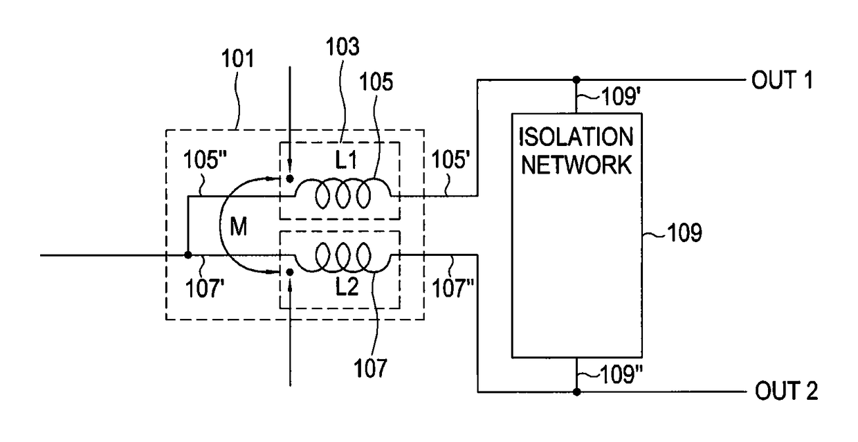
[0024]Although inductors are described as inductive elements in this disclosure, transmission lines or inductors may be included as elements having an inductance.

[0025]A conventional Wilkinson power combiner / divider that is widely used in wireless communication devices will now be described. The Wilkinson power combiner / divider is a passive microwave element having a phase difference of 0 degrees between two output ports and is primarily used to evenly distribute power. The Wilkinso...


PUM


Abstract

Disclosed is a power divider circuit providing a mutual inductance and including a first primary inducing element having a first terminal connected with a first output port and a second terminal connected with a second primary inducing element having a first terminal connected with a second output port and a second terminal connected with the first primary inducing element and magnetically and mutually coupled with the first primary inducing element, a sub inducing element having a first terminal connected with an input port and a second terminal connected with the second terminal of the first primary inducing element and the second terminal of the second primary inducing element, and an isolation network connected between the first output port and the second output port. The sub inducing element is magnetically and mutually coupled with each of the first primary inducing element and the second primary inducing element.

Description

PRIORITY[0001]This application claims priority under 35 U.S.C. § 119(a) to a Korean Patent Application filed in the Korean Intellectual Property Office on Dec. 7, 2015 and assigned Serial No. 10-2015-0173141, the contents of which are incorporated herein by reference.BACKGROUND[0002]1. Field of the Disclosure[0003]The present disclosure relates generally to power combiners / dividers, and more particularly, to power combiners / dividers that use mutual inductance.[0004]2. Description of the Related Art Current fourth generation partnership project (4G) long term evolution (LTE) systems enable high-rate data communications up to at least 100 Mbps. However, there is increasing demand for high-rate data transmission using wireless communication.[0005]One method for meeting this demand is to use millimeter wave band frequencies. The use of a 28 GHz and 60 GHz band frequency allows for use of a bandwidth of at least 800 MHz. The use of a broad band enables communication at a 1 Gbps or higher...

Claims


Application Information

Patent Timeline
Patent Type & Authority Patents(United States)
IPC IPC(8): H01P5/12H03H7/38H03H7/46
CPCH03H7/38H03H7/46H03H7/48
Inventor LEE, JEONG-HOKIM, CHOUL-YOUNGOH, HYUN-MYUNGBYEON, CHUL-WOOSON, JU-HO
Owner SAMSUNG ELECTRONICS CO LTD
Why Eureka
Try Eureka