Unwind for printer

a printer and unwinding technology, applied in typewriters, thin material handling, printing, etc., can solve problems such as obviating problems, and achieve the effect of low cos

Active Publication Date: 2006-08-24
AVERY DENNISON CORP
View PDF19 Cites 15 Cited by
  • Summary
  • Abstract
  • Description
  • Claims
  • Application Information

AI Technical Summary

Benefits of technology

[0005] The invention relates to an improved, low cost, apparatus that can print on both si...

Problems solved by technology

This obviates the problems of a prior art...

Method used


Image

  • Unwind for printer
  • Unwind for printer
  • Unwind for printer

Examples


Embodiment Construction

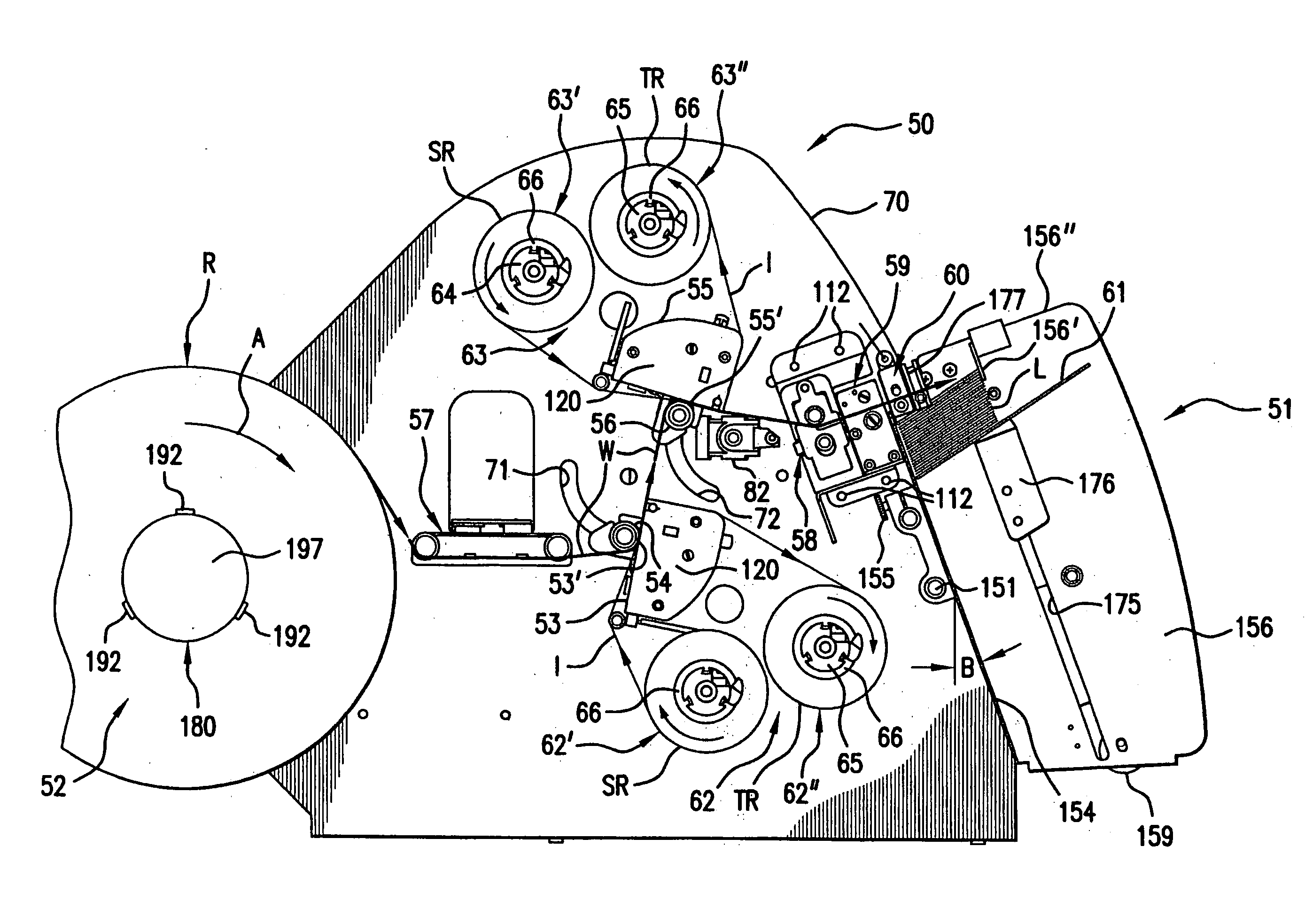
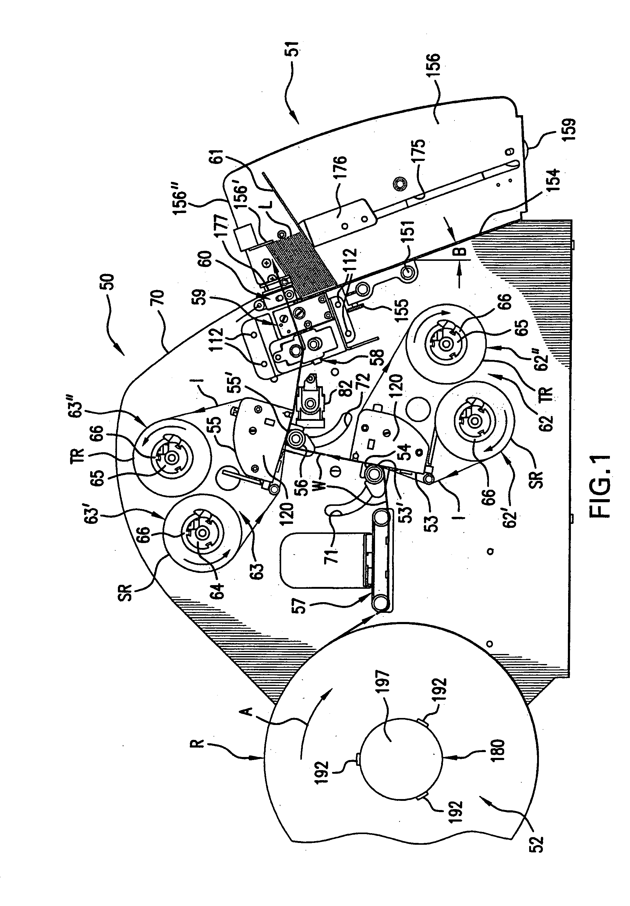
[0064] With reference initially to FIG. 1, there is shown a printer generally indicated at 50 for printing on a printable web W and a stacker generally indicated at 51. The web W is initially in the form of a wound supply roll R mounted on an unwind mechanism generally indicated at 52. The web W is drawn through the printer 50 in the direction of arrows shown along the path of the web W. As the web W is paid out of the web roll R, the web roll R rotates clockwise in the direction of arrow A. The unwind mechanism 52 applies a slight tensioning force to the web W by attempting to rotate the roll R counterclockwise, that is, in a direction opposite to the direction of the arrow A. However, the force exerted on the web W to feed the web W through the printer 50 overcomes the force exerted by the unwind mechanism to enable the web W to be fed through the printer 50. By this arrangement the web W is always maintained under the desired tension.

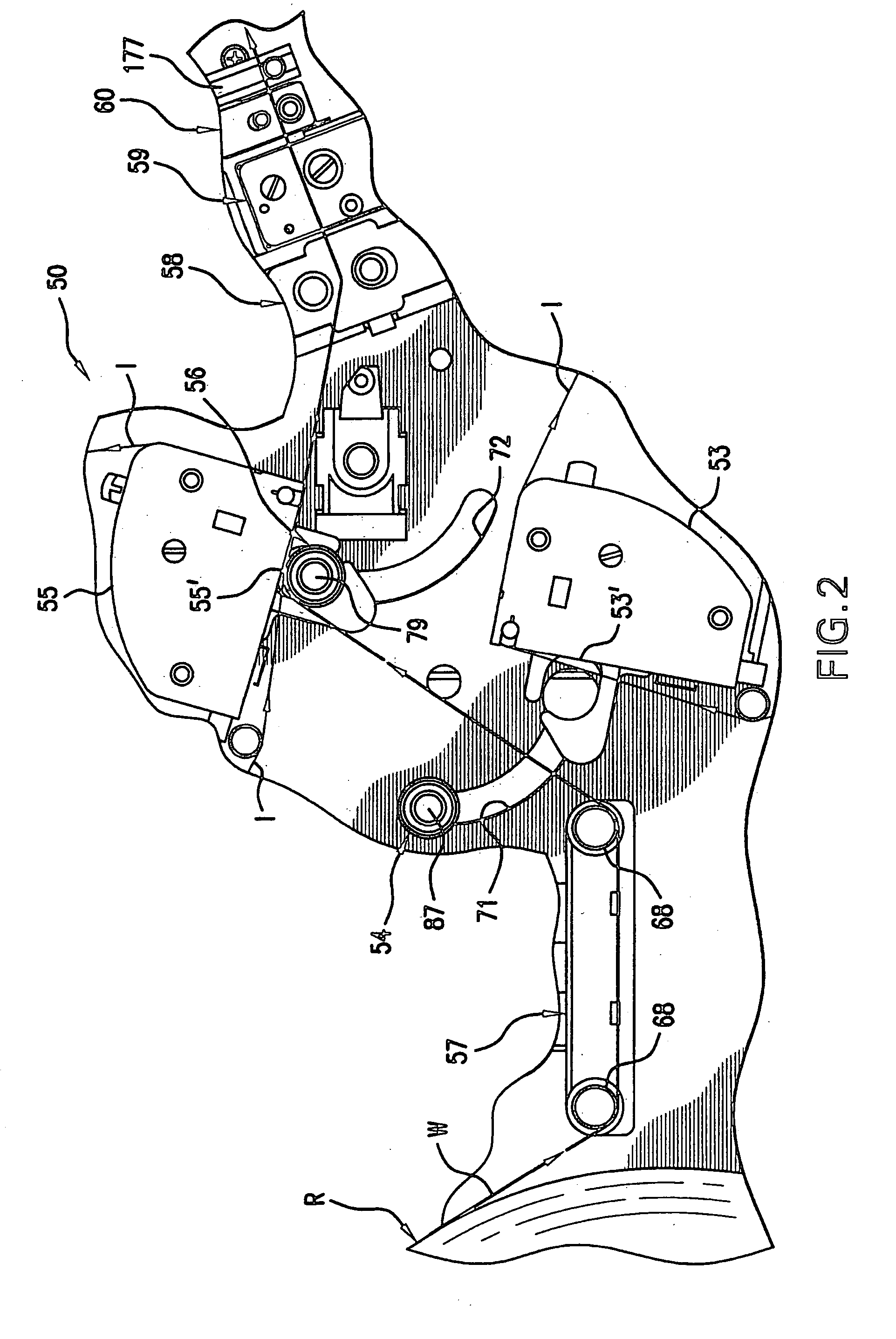
[0065] The printer 50 includes a print head a...


PUM


Abstract

Disclosed are a printer and a stacker and methods. The printer prints selectively on one or both sides of a printable web and sheets or labels are cut from the web and stacked in the stacker. The printer has an unwind or unwind mechanism that accepts and holds web rolls of different widths in center-justified relationship with respect to a print head. The printer has a spindle for mounting an ink ribbon core with a detent for center-justifying the ink-ribbon with respect to the print head.

Description

CROSS-REFERENCE TO RELATED APPLICATIONS [0001] This U.S. patent application is a continuation-in-part of Ser. No. 10 / 779,990 filed Feb. 17, 2004. [0002] Another U.S. patent application entitled “DECURLING TAG WEBS IN PRINTERS / STACKERS”, filed on even date herewith, wherein the named inventors are Raymond A. Blanchard, Jr. and Donald J. Ward, Docket M-667, has a disclosure the entirety of which is incorporated by reference, and that application discloses features of the printer not disclosed in application Ser. No. 10 / 779,990.FIELD OF THE INVENTION [0003] This invention relates to the field of printers and stackers and to methods of printing and stacking labels. BACKGROUND OF THE INVENTION [0004] The following prior art is made of record: U.S. Pat. Nos. 3,565,360; 3,596,846; 3,799,465; 4,278,112; 4,418,618; 4,813,626; 4,991,785; 5,241,407; 5,486,259; 5,695,291; 5,785,442; 5,820,277; 5,833,377; 5,961,228; 6,059,468; 6,078,345; 6,142,622; 6,164,203; 6,241,407; 6,336,760; 6,338,452; 6,3...

Claims


Application Information

Patent Timeline
IPC IPC(8): B41J15/02B41J3/407B41J3/60B41J15/04B65H16/04B65H75/24
CPCB41J3/54B41J3/60B41J11/0025B41J15/02B65H16/04B65H16/06B65H23/02B65H75/242B65H75/248B65H2301/3611B65H2301/41369B65H2403/52B65H2511/12B65H2701/192B65H2701/372B65H2801/12B65H2220/04
Inventor WARD, DONALD J.
Owner AVERY DENNISON CORP
Why Eureka
Try Eureka