Wrapping machine

a film dispenser and roller technology, applied in the field of wrapping machines, can solve the problems of increasing the size of the film dispenser in the vertical direction, the extension of the rollers, and the large size of the film dispenser provided with an openable gate section, etc., and achieves the effects of light weight, simple and cheap, and convenient feeding

Inactive Publication Date: 2005-03-10
M HALOILA
View PDF8 Cites 13 Cited by
  • Summary
  • Abstract
  • Description
  • Claims
  • Application Information

AI Technical Summary

Benefits of technology

[0011] A specific object of the invention is to disclose a wrapping machine in which the end of the film can be easily fed in via deflecting pinch rollers and pre-stretching rollers without a need to divide the frame of the film dispenser into a fixed part and an openable part or to provide any tapered extensions at the ends of the pre-stretching rollers.
[0012] A further object of the invention is to disclose a wrapping machine in which the film dispenser has as compact a size in the vertical direction as possible and is light, simple and cheap.

Problems solved by technology

A problem with this prior-art solution is, however, that the film dispenser provided with an openable gate section is fairly big and heavy.
In addition, the structure is expensive and relatively complicated.
A problem with the structure according to this EP patent is that the extensions of the rollers increase the size of the film dispenser in the vertical direction.

Method used


Image

  • Wrapping machine
  • Wrapping machine
  • Wrapping machine

Examples


Embodiment Construction

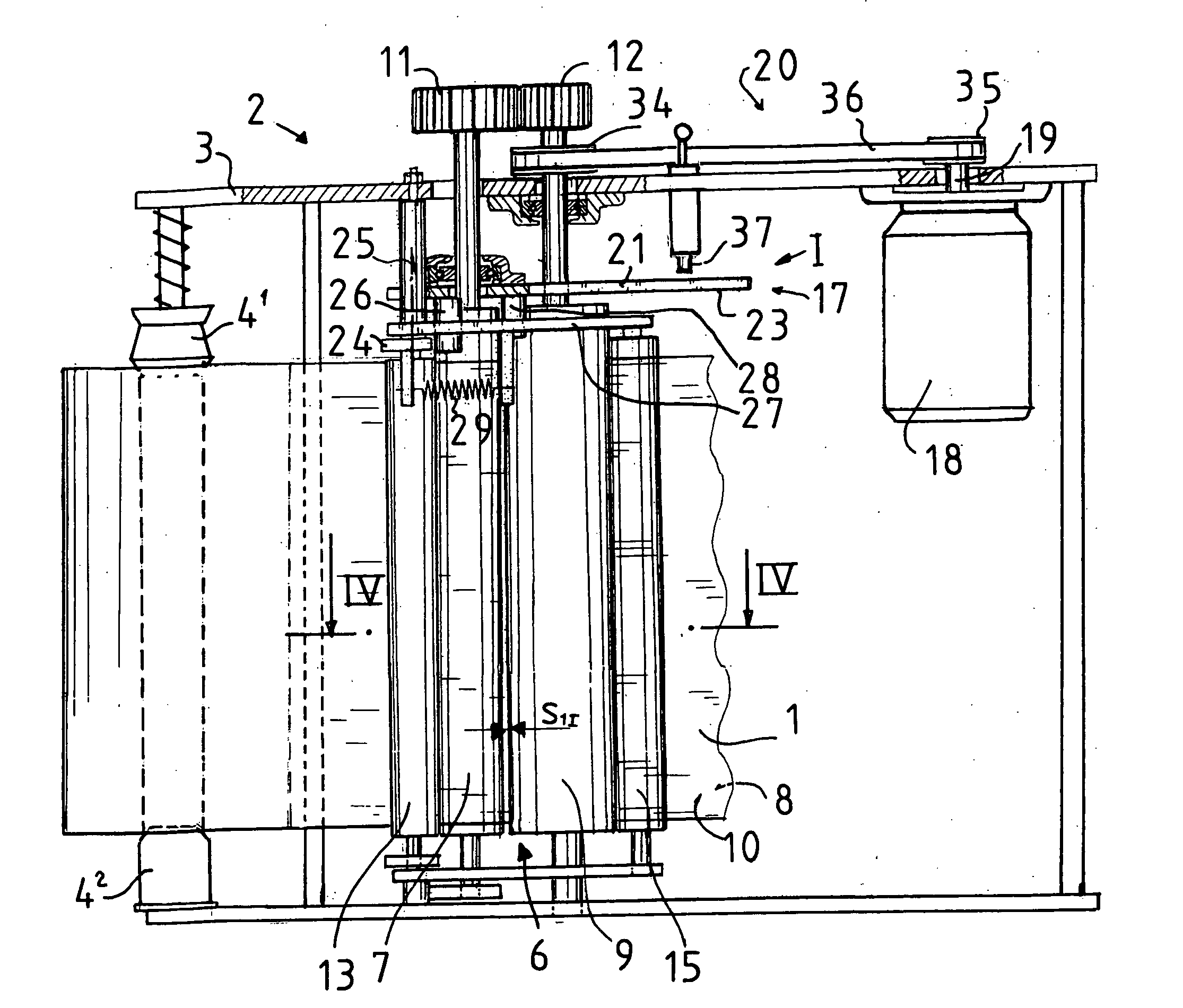
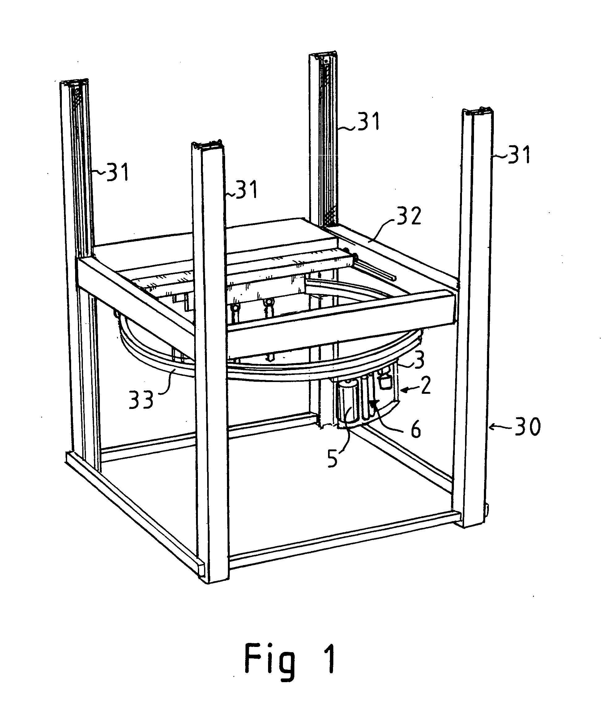
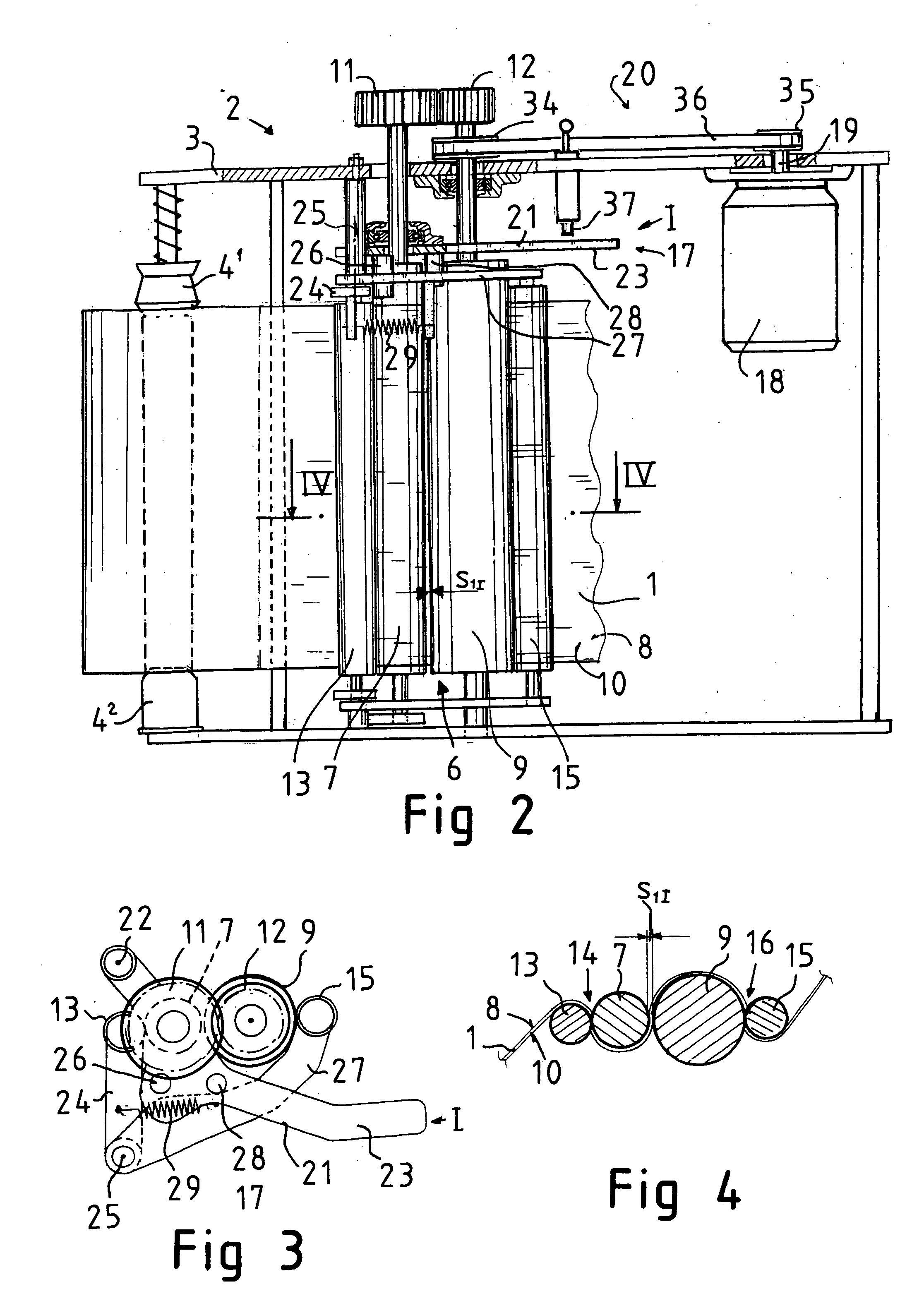
[0033]FIG. 1 presents a wrapping machine for wrapping a wrapping film web 1 around an object (not shown) to be packaged.

[0034] The wrapping machine 1 comprises a machine frame 30, which is supported on a fixed floor. The machine frame 30 comprises four vertical upright columns 31 at a distance from each other in a rectangular arrangement such that each upright column 31 is located at a corner of an imaginary rectangle. A lifting frame 32 has been arranged to be movable upwards and downwards in a vertical direction by means of a hoisting motor (not shown).

[0035] A film dispenser 2, on which a film web roll 5 can be rotatably supported, guided by a ring arrangement 33, has been arranged to circulate on a circular path around the object to be packaged so that the plastic film web 1 is delivered from the film web roll 5, forming a wrapping around the object to be packaged. When the ring arrangement 33 supporting the film dispenser 2 is simultaneously moved vertically by moving the lif...


PUM

PropertyMeasurementUnit
distanceaaaaaaaaaa
circumferential velocitiesaaaaaaaaaa
structureaaaaaaaaaa

Abstract

A wrapping machine having a pre-stretching device for pre-stretching a film web drawn from film roll before its being wrapped around an object, said pre-stretching device including a first pre-stretching roller and a second pre-stretching roller, which are tractively coupled via power transmission gears. A first deflecting pinch roller has been fitted to be pressed against the first pre-stretching roller to form a first nip for the film web passed between the first deflecting pinch roller and the first pre-stretching roller. A second deflecting pinch roller has been fitted to be pressed against the second pre-stretching roller to form a second nip for the film web passed between the second deflecting pinch roller and the second pre-stretching roller. A lever mechanism moves the first pre-stretching roller between an engagement position and a disengagement position, so that the lever mechanism also moves the first deflecting pinch roller apart from the first pre-stretching roller and simultaneously the second deflecting pinch roller apart from the second pre-stretching roller to allow easier thread-in of the film web end.

Description

FIELD OF THE INVENTION [0001] The present invention relates to a wrapping machine as defined in the preamble of claim 1. BACKGROUND OF THE INVENTION [0002] In prior art, a wrapping machine as defined in the preamble is known from specification U.S. Pat. No. 5,875,616. [0003] Specification U.S. Pat. No. 5,875,616 discloses a wrapping machine for winding a wrapping film web around an object to be packaged. The wrapping machine comprises a film dispenser, which comprises a frame. The frame is provided with supporting elements for rotatably supporting a film web roll on the frame. [0004] The film dispenser comprises a pre-stretching device connected to the frame for pre-stretching the film web drawn from the film web roll before its being wrapped around the object. The pre-stretching device comprises a first pre-stretching roller, with the outer surface of whose rim the first side of the film web drawn from the roller can be brought into a tractive frictional contact. The pre-stretching...

Claims


Application Information

Patent Timeline
Patent Type & Authority Applications(United States)
IPC IPC(8): B65B11/00B65B11/02B65H23/14
CPCB65B11/025B65B2210/18B65B2011/002
Inventor SUOLAHTI, YRJO
Owner M HALOILA
Why Eureka
Try Eureka