Coil forming method and coil forming device

a coil and forming device technology, applied in the manufacture of stator/rotor bodies, inductance/transformers/magnets, dynamo-electric components, etc., to achieve the effect of easy alignment and easy alignmen

Inactive Publication Date: 2005-06-23
AISIN AW CO LTD
View PDF4 Cites 28 Cited by
  • Summary
  • Abstract
  • Description
  • Claims
  • Application Information

AI Technical Summary

Benefits of technology

[0018] In the method of the present invention, it is preferred that the bobbin being wound with the electric wire is extended relative to the remaining bobbins. In this case, the extended (protruding) bobbin can be easily fed with the electric wire in a direction perpendicular to the winding axis thereof. Therefore, it is easy to feed the electric wire and to wind the electric wire around the bobbin, so that the single-pole coil can be more easily formed with little twist.
[0034] Moreover, it is preferred that each of the bobbins has removably mounted shaping blocks for shaping the single-pole coil to be wound. In this case, the shape of the single-pole coil can be easily changed by employing shaping blocks of different shapes.

Problems solved by technology

However, the coil forming method of the prior art thus far described has the following problems.

Method used


Image

  • Coil forming method and coil forming device
  • Coil forming method and coil forming device
  • Coil forming method and coil forming device

Examples


embodiment 1

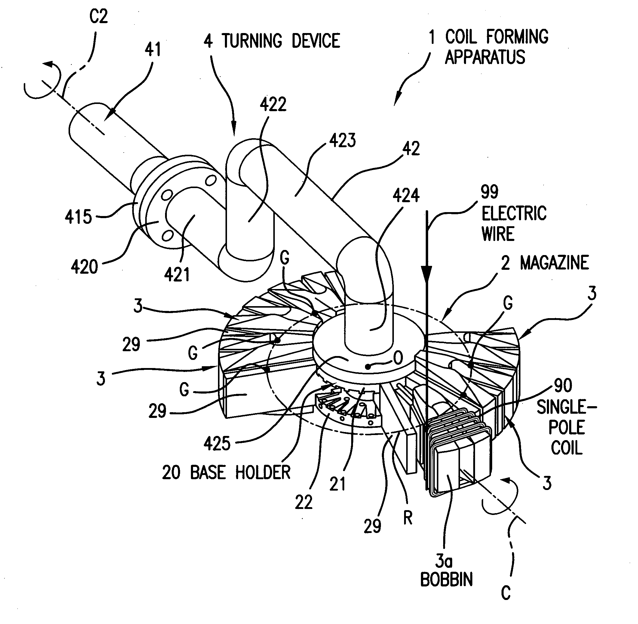
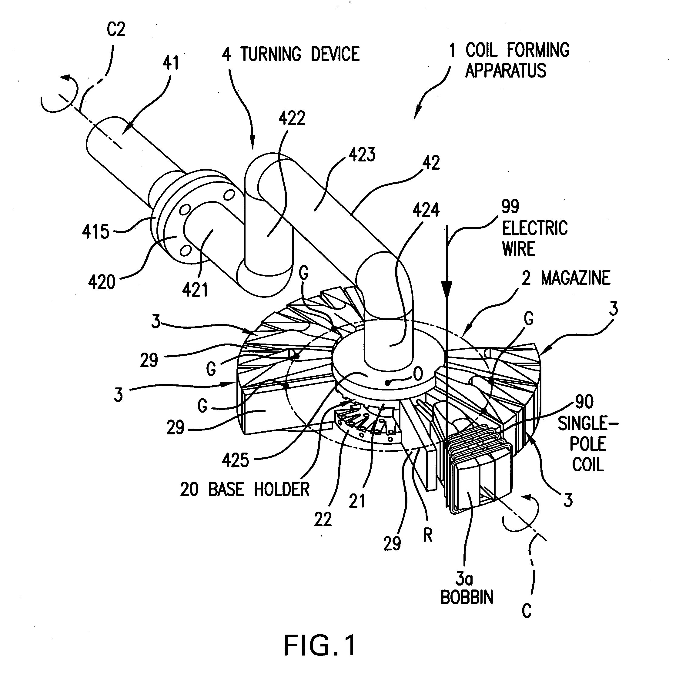
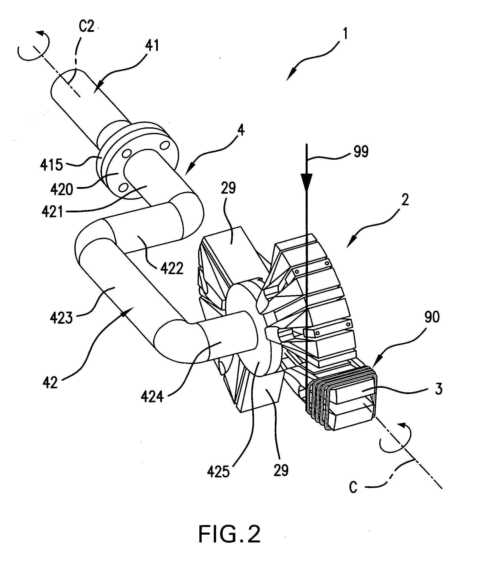
[0081] A coil forming method and a coil forming apparatus according to an embodiment of the invention will now be described with reference to FIG. 1 to FIG. 17.

[0082] As shown in FIG. 1 and FIG. 2, a coil forming apparatus 1 forms a motor coil 9 (see FIG. 14) composed of three contiguous single-pole coils 90 formed of an electric wire 99 wound into a loop shape. The coil forming apparatus 1 includes a winding jig 2 and a turning device (“rotation means”) 4.

[0083] As shown in FIG. 1 to FIG. 3, the winding jig 2 is provided with a base holder (“indexing means”) 20 and a plurality of bobbins 3 arranged on the outer circumference of the base holder 20. These bobbins 3 are arranged to move toward and away from the base holder 20 and are constructed such that any one can be extended farther than the others.

[0084] As shown in FIG. 1 and FIG. 2, the turning device 4 is constructed to turn the winding jig 2 as a whole around an axis C for winding in the forward or reverse direction around...

embodiment 2

[0131] This embodiment presents one example of the method for inserting the motor coils formed by using the coil forming apparatus 1 of the first embodiment, directly into the stator core from the winding jig 2.

[0132] In this second embodiment, the motor coils 9 (see FIG. 14) are inserted into slots 810 formed in the inner circumferential surface of a ring-shaped stator core 81, as shown in FIG. 18 and FIG. 19. Here in this embodiment, the motor coils 9 (or the single-pole coils 90) are omitted to clarify the motions of insertion blades 734 or the like, as will be described hereinafter.

[0133] The motor to be constructed of the stator core 81 is a three-phase DC brushless motor. Moreover, the stator core 81 in this embodiment is prepared by laminating ring-shaped electromagnetic steel sheets. The stator core 81 is provided with an inner circumferential surface with the slots 810 for receiving the coils, as shown in FIG. 18 and FIG. 19.

[0134] In this embodiment, the stator core 81 ...

embodiment 3

[0148] As shown in FIG. 20 to FIG. 22, this third embodiment presents a detailed example of a coil inserting apparatus to be used to transfer the coils from the winding jig 2 into the stator core 81.

[0149] The coil inserting apparatus 6 is supported on a bottom plate 61, as shown in FIG. 20 and FIG. 21, with a plurality of first arms 64 arranged to rock on fulcrums 641, and a plurality of second arms 65 arranged to rock on fulcrums 651. As shown in FIG. 20 and FIG. 22, each first arm 64 carries the two insertion blades 73 at its upper end, and each second arm 65 carries the two provisional shaping blades 734 at its upper end.

[0150] The first arm 64 is provided with a slot 642, which can engage with a pin 663 embedded on a lifting plate 661. The second arm 65 is also provided with a slot 652, which can engage with a pin 664 also embedded on the lifting plate 661.

[0151] Lifting plate 661 is connected to a cylinder 671, a lifting rod 672, a base plate 673, connecting rods 674 and so...


PUM

PropertyMeasurementUnit
angleaaaaaaaaaa
circumferenceaaaaaaaaaa
centers of gravityaaaaaaaaaa

Abstract

A coil forming apparatus for forming a continuous-pole coil having a plurality of single-pole coils includes a winding jig rotatable around a center swing axis. The winding jig includes: a holder rotatable around a center axis of rotation different from center swing axis; and a plurality of coil bobbins arranged around said holder and mounted for reciprocal movement between advanced and retracted positions relative to the holder. Each individual coil bobbin has a winding axes which can be aligned with the center swing axis by turning the winding jig around the center axis of rotation. The single-pole coils having little twist can be stably formed for any coil bobbin to thereby form the continuous-pole coil.

Description

CROSS-REFERENCE TO RELATED APPLICATIONS [0001] This application is a National Phase Application (35 USC 371) of PCT / JP2003 / 010145 and claims priority of Japanese Application No. 2002-231978 filed Aug. 8, 2002 and Japanese Application No. 2003-116241 filed Apr. 21, 2003.INCORPORATION BY REFERENCE [0002] The disclosure of Japanese Patent Application No. 2002-231978 filed Aug. 8, 2002 and Japanese Application No. 2003-116241 filed Apr. 21, 2003 including the specifications, drawings and abstracts are incorporated herein by reference in their entirety. [0003] 1. Technical Field [0004] The present invention relates to an apparatus and a method for forming a coil to be used in a motor (e.g., an electric motor). [0005] 2. Background Art [0006] When a motor including a stator having a plurality of single-pole coils inserted in the slots of a stator core is to be manufactured, for example, it is necessary to form a coil as a plurality of continuous single-pole coils. [0007] In the coil formi...

Claims


Application Information

Patent Timeline
Patent Type & Authority Applications(United States)
IPC IPC(8): H02K15/02H02K15/04H02K15/06
CPCH02K15/022H02K15/0457Y10T29/49009H02K15/068H02K15/066H02K15/0442H01F41/06
Inventor HASHIMOTO, SHINGOKUROYANAGI, TOORUYAMAGUCHI, TSUYOSHI
Owner AISIN AW CO LTD
Why Eureka
Try Eureka