
Conformal microstrip leaky wave antenna

a leaky wave antenna and microstrip technology, applied in the direction of leaky waveguide antennas, antenna details, antennas, etc., can solve the problems of reducing efficiency, reducing the relative narrowness of such antennas, and reducing efficiency, so as to improve the leaky wave traveling wave antenna array, reduce the emission of undesirable cross polarized radiation components, and facilitate feeding

Inactive Publication Date: 2006-09-19
AIR FORCE UNITED STATES OF AMERICA AS REPRESENTED BY THE SEC OF THE
View PDF6 Cites 30 Cited by
  • Summary
  • Abstract
  • Description
  • Claims
  • Application Information

AI Technical Summary

Benefits of technology

[0022]It is another object of the invention to provide a traveling wave antenna having high efficiency and an end-fire radiation pattern.
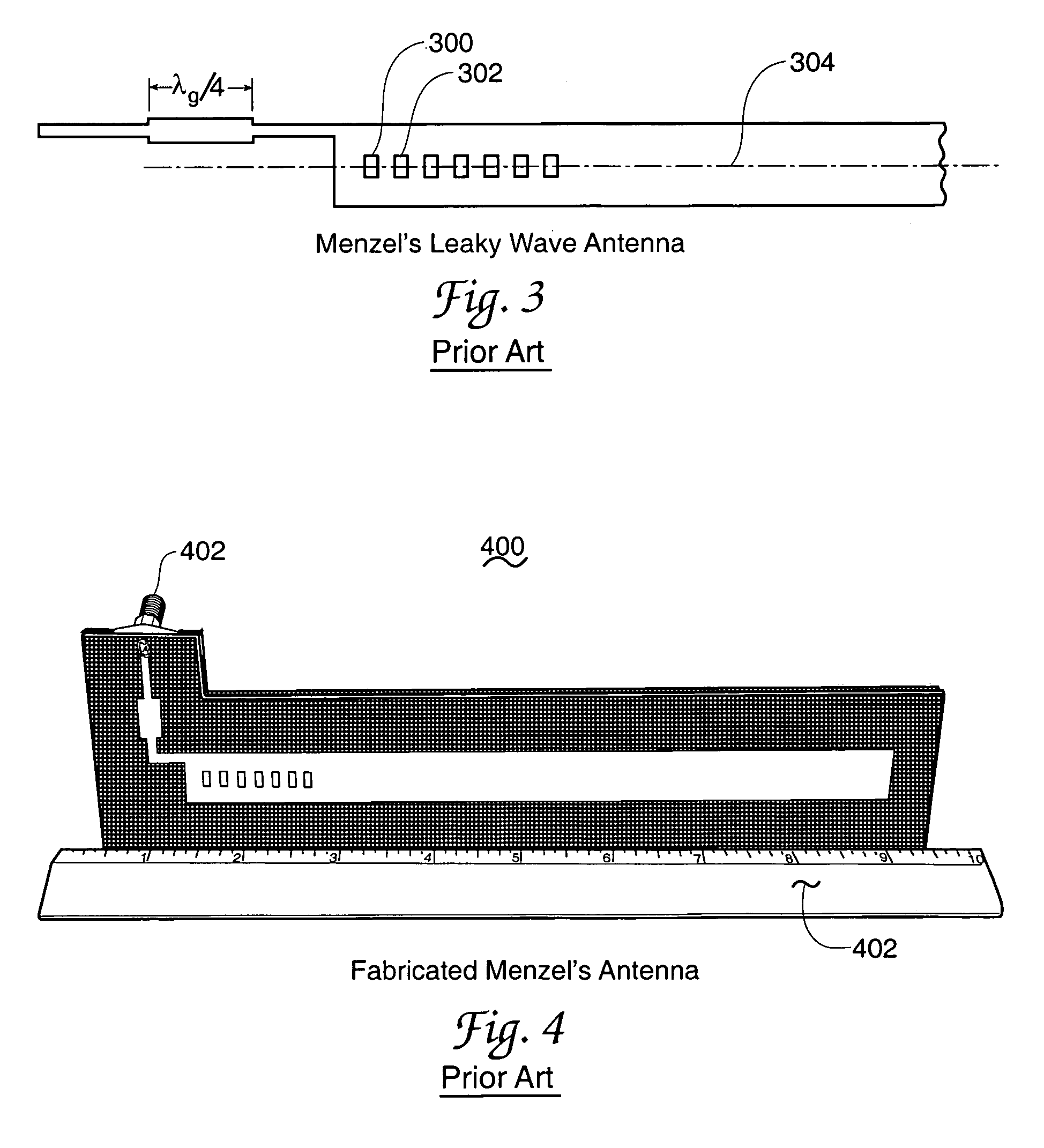
[0027]It is another object of the invention to provide an improved leaky wave type of traveling wave antenna in which omission of active element slots used in a related prior art Menzel antenna precludes existence of slot sourced antenna emissions and hence enables lower emission of undesirable cross polarized radiation components.
[0028]It is another object of the invention to provide an improved leaky wave traveling wave antenna in which use of shorting based suppression of fundamental mode energy propagation in a microstrip transmission line element is advantageous over the slot achieved suppression of fundamental mode energy propagation employed in a related prior art Menzel antenna.
[0029]It is another object of the invention to provide an improved leaky wave antenna that is easier to feed than previous higher order mode leaky wave antennas.
[0030]It is another object of the invention to provide an improved leaky wave traveling wave antenna array in which a reduced degree of mutual coupling between array elements is achieved.

Problems solved by technology

These desired antenna characteristics typically are, however, conflicting in nature and thus an antenna engineer must often make trade-offs amongst these needs.
One of the major challenges associated with the patch antenna is however, the relatively narrow bandwidth such an antenna achieves [4].
Increasing the substrate thickness used with these antennas can increase this bandwidth; however, surface waves can be excited in such patch antennas and this leads to a rather serious reduction in efficiency.
This reduction can be limited by the introduction of shorting pins, or a cavity that have the effect of squelching surface waves.
Moreover since patch antennas are usually used in large arrays, in part because of their low cost and low gain, shorting pins or cavities cannot always be used due to the proximity of the antenna elements to each other.
The result is strong surface wave coupling between adjacent antennas and this complicates the antenna synthesis task.
Alternative feeding mechanisms can be used to increase the achieved bandwidth, without exciting surface waves; however, the achievable bandwidth is typically on the order of 20% to 60% [5] but certainly bandwidths of 2:1 or 10:1 are not achievable with any manner of feeding a patch antenna.
However, the relatively high efficiency that can otherwise be achieved with patch antennas requires low loss magnetic materials.
Such materials are difficult to realize at high frequencies, at frequencies greater than 1 gigahertz for example.
However, it is a well-known fact that for a finite array of elements, there are scan limits on the beam for such elements.

Method used


Image

  • Conformal microstrip leaky wave antenna
  • Conformal microstrip leaky wave antenna
  • Conformal microstrip leaky wave antenna

Examples


Embodiment Construction

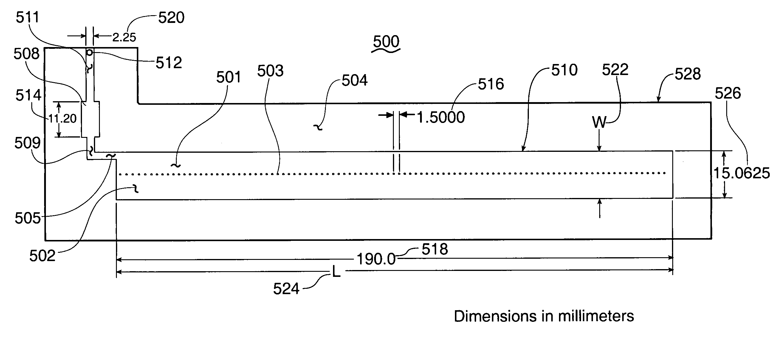
[0059]The antenna of the present invention is an inherently wide bandwidth antenna belonging to the general class of traveling wave antennas. Such traveling wave antennas also include the Beverage-can antenna and the rhombic antenna for examples. Antennas of this type utilize a load element at the end of the antenna to dampen undesirable back energy wave reflections and thus have a limit on their efficiency since the energy dissipated in this load is not radiated. As these antennas become electrically longer however, the main beam of the antenna desirably squints towards the direction of propagation and this characteristic tends to overcome the load energy loss. An enlightening overview of wide bandwidth antennas is disclosed in reference [3] herein; this reference and each of the other references identified in this document are hereby incorporated by reference herein.

[0060]The presently desired performance aircraft conformal version of a traveling wave antenna can be implemented us...


PUM


Abstract

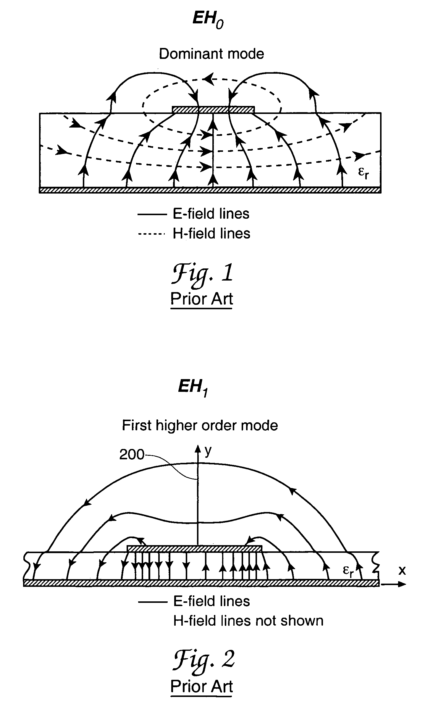
A microwave radio frequency bidirectional energy flow-capable antenna method and related antenna of the physically conformal microstrip transmission line, traveling wave and leaky wave characterizations; the antenna is especially suited to vehicle mounting. The disclosed antenna operates in an EH1 or other above dominant mode energy wave propagation configuration, a configuration at least partially achieved by an array of selected-location radiating element shortings to an antenna-underlying transmission line ground plane element. Comparisons of the disclosed antenna with characteristics of a similarly classified antenna of somewhat lesser desirable but know characteristics are included.

Description

RIGHTS OF THE GOVERNMENT[0001]The invention described herein may be manufactured and used by or for the Government of the United States for all governmental purposes without the payment of any royalty.BACKGROUND OF THE INVENTION[0002]One of the “Holy Grails” for antenna engineers working in the aircraft and other vehicle fields, where aerodynamic drag and vehicle profile are important, is achieving an antenna with wide bandwidth, high efficiency, a convenient radiation pattern, and a small addition to vehicle profile. This latter characteristic may be considered, with the use of other words, as a need for a vehicle “conformal antenna.” The need for these characteristics extends significantly into the world of the stealth aircraft since non-conformal protuberances on an airframe provide a substantial radar signal reflection or return point addition to the aircraft's radar signature. These desired antenna characteristics typically are, however, conflicting in nature and thus an antenn...

Claims


Application Information

Patent Timeline
Patent Type & Authority Patents(United States)
IPC IPC(8): H01Q1/38
CPCH01Q1/38H01Q13/206H01Q13/20
Inventor THIELE, GARY A.JANNING, DAN S.
Owner AIR FORCE UNITED STATES OF AMERICA AS REPRESENTED BY THE SEC OF THE
Learn More