A detachable coupling arrangement for connecting a handle to a utensil

a technology of detachable coupling and utensil, which is applied in the direction of metal-working hand tools, kitchen equipment, fastening means, etc., can solve the problems of user's inability to remove the handle, spillage or accidents, and cooking accessories with non-removable handles are often difficult to wash and stor

Active Publication Date: 2018-06-28
VERSUNI HLDG BV
View PDF0 Cites 62 Cited by
  • Summary
  • Abstract
  • Description
  • Claims
  • Application Information

AI Technical Summary

Benefits of technology

[0006]It is an object of the invention to provide a detachable coupling arrangement for connecting a ...

Problems solved by technology

Cooking accessories often comprise a handle to hold the accessories, and the user is unable to remove the handle.
However, cooking accessories with non-removable handles are often difficult to wash and store.
Furthermore, the handles can get knocked during cooking and result in spillages or accidents.
However, known removable handles ar...

Method used


Image

  • A detachable coupling arrangement for  connecting a handle to a utensil
  • A detachable coupling arrangement for  connecting a handle to a utensil
  • A detachable coupling arrangement for  connecting a handle to a utensil

Examples


first embodiment

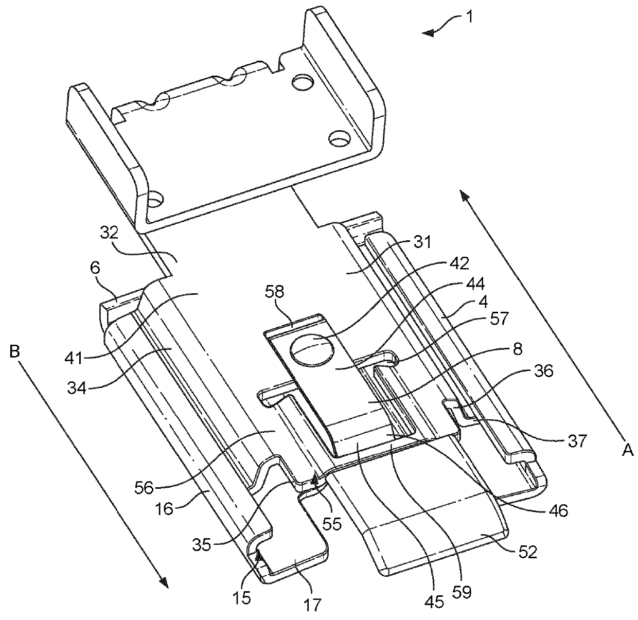
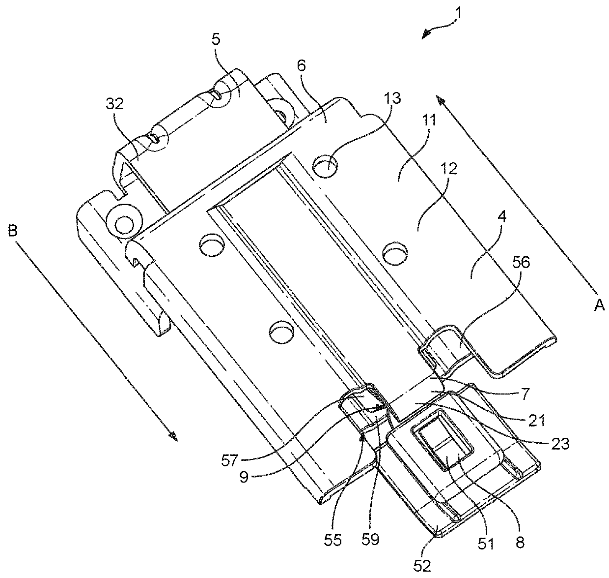
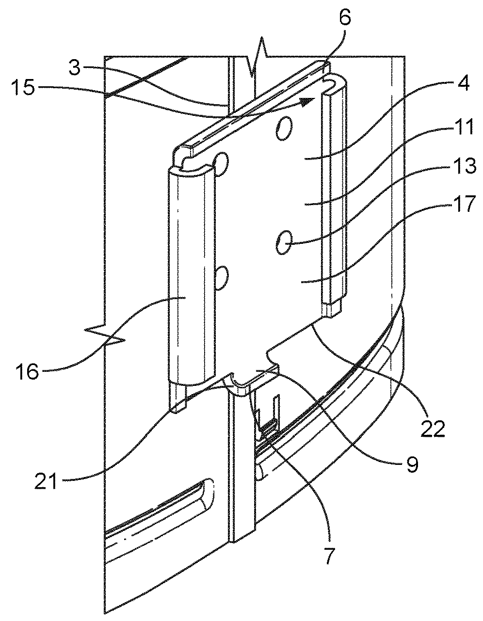
[0053]FIG. 1 and FIG. 2 depict the present invention. In this embodiment, there is provided a detachable coupling arrangement 1 for connecting a handle 2, shown in FIG. 4, to a utensil 3, shown in FIG. 3, comprising a female portion 4 and a male portion 5 adapted to cooperate with the female portion 4. The detachable coupling arrangement 1 further comprises a stop element 6 for preventing movement of the male portion 5 relative to the female portion 4 in an upward direction A when the female portion 4 is coupled to the male portion 5. The detachable coupling arrangement 1 further comprises a first retention element 7 and a resiliently deformable second retention element 8 configured to cooperate to prevent movement of the male portion 5 relative to the female portion 4 in a downward direction B when the female portion 4 is coupled to the male portion 5. The first retention element 7 has a retention surface 9 and the second retention element 8 is configured to locate over the first r...

second embodiment

[0104]In the second embodiment, the female portion 4 comprises an aperture 66. The aperture 66 is preferably located centrally in a base section 11 of the female portion 4. The base section 11 of the female portion 4 is preferably raised and configured to cooperate with the male portion 5. The base section 11 is raised to receive a projection 34 of the male portion 5 behind a front surface 17 of the female portion 4.

[0105]Due to the central aperture 66 for receiving the male portion 5, the second exemplary embodiment comprises two protrusions 21 of a first retention element 7. One protrusion 21 extends from a bottom wall 22 of the base section 11 on either side of the aperture 66. The protrusions 21 are preferably identical to one another and configured to cooperate with a second retention element 8.

[0106]In the second embodiment, the male portion 5 comprises a single projection 34. The projection 34 is, preferably, also located centrally and is configured to cooperate with slots 15...

third embodiment

[0109]FIG. 9 shows a cross-sectional view of a detachable coupling arrangement 71 of the present invention. The detachable coupling arrangement 71 is an interlocking handle embodiment. In such an embodiment, the female or male portions 4, 5 may have a stop element 6. Furthermore, the detachable coupling arrangement 71 can be arranged so that the portion attached to a handle 2 can be female or male.

[0110]In the third embodiment, the female portion 4 may be mounted on the utensil 3 and the male portion 5 may be mounted on the handle 2. The female portion 4 preferably comprises a horizontal flange 72 extending from the utensil 3 and a vertical plate 73. The horizontal flange 72 may act as a stop element 6 to stop upwards movement of the male portion 5. The vertical plate 73 may comprise one or more slots (not shown), as described in previous embodiments, on the side of the vertical plate 73 facing the utensil. The side of the vertical plate 73 facing away from the utensil 3 preferably ...


PUM


Abstract

The present application relates to a detachable coupling arrangement (1) for connecting a handle (2) to a utensil, the detachable coupling arrangement (1) comprises a male portion (5), a female portion (4) adapted to receive the female portion (4), a stop element (6) for preventing movement of the male portion (5) relative to the female portion (4) in an upward direction (A) when the female portion (4) is coupled to the male portion (5). The detachable coupling arrangement (1) also comprises a first retention element and a resiliently deformable second retention element (8) configured to cooperate to prevent movement of the male portion (5) relative to the female portion (4) in a downward direction (B) when the female portion (4) is coupled to the male portion (5), the first retention element having a retention surface and a lower surface (23), and the second retention element (8) being configured so that it engages the lower surface (23), as the male portion (5)is received in the female portion (4), to resiliently deform the second retention element (8) so that it locates over the first retention element and abuts against the retention surface.

Description

FIELD OF THE INVENTION[0001]The present invention relates to a detachable coupling arrangement for connecting a handle to a utensil. The present invention also relates to a handle and a utensil comprising cooperating portions of the detachable coupling arrangement and, in particular, an appliance for an air-based fryer product comprising the handle and utensil.BACKGROUND OF THE INVENTION[0002]Cooking accessories often comprise a handle to hold the accessories, and the user is unable to remove the handle. The advantage of this situation is that the accessory, a pan, for example, cannot fall off of the handle. However, cooking accessories with non-removable handles are often difficult to wash and store. Furthermore, the handles can get knocked during cooking and result in spillages or accidents.[0003]It is known to use a removable handle for cooking utensils. Being able to remove the handle from a cooking utensil may help to reduce accidentally knocking the cooking utensils off of a s...

Claims


Application Information

Patent Timeline
IPC IPC(8): A47J45/07B25G3/18F16B21/07
CPCA47J45/071B25G3/18F16B21/071A47J37/0641A47J45/07
Inventor BONACCORSO, DAVIDE
Owner VERSUNI HLDG BV
Why Eureka
Try Eureka