Ultrasonic sealing anvil

Active Publication Date: 2018-07-05
TOPPAN PRINTING CO LTD
View PDF1 Cites 2 Cited by
  • Summary
  • Abstract
  • Description
  • Claims
  • Application Information

AI Technical Summary

Problems solved by technology

Faster processing with ultrasonic sealing may accordingly impair the positioning accuracy between the recess of the anvil and the sealing part, causing misalignment of the overlap

Method used


Image

  • Ultrasonic sealing anvil
  • Ultrasonic sealing anvil
  • Ultrasonic sealing anvil

Examples


Embodiment Construction

[0022]An embodiment of the present invention will be described below. Also, variations should be evident to one of skill in the art. It is to be understood that the description below is intended to be representative of the present invention, and that the present invention is not necessarily limited to the description below.

[0023]The present embodiment describes an ultrasonic sealing anvil (hereinafter may be simply referred to as an “anvil”) by way of an example of producing a package having an appearance of a substantially rectangular prism filled with a liquid. The package described in the present embodiment can store contents, for example, a liquid such as juice or an alcoholic beverage, or solid contents for a long period of time.

[0024](Overall Configuration)

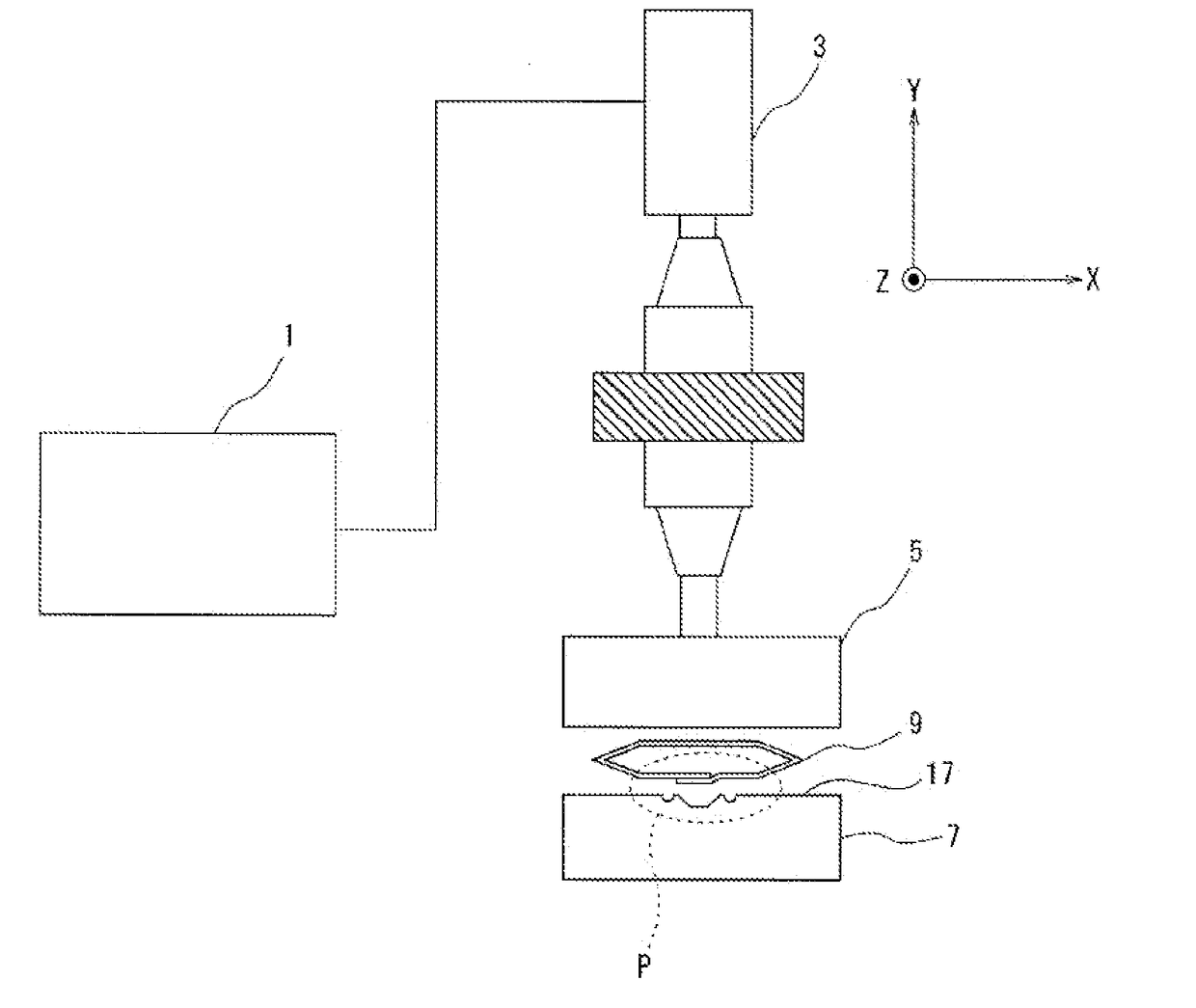
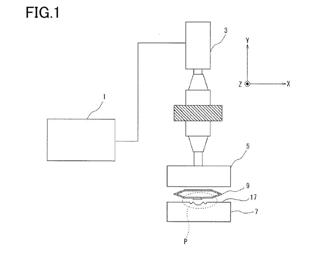
[0025]FIG. 1 is a schematic diagram illustrating an ultrasonic sealing apparatus that uses an anvil of the present embodiment. The ultrasonic sealing apparatus shown in FIG. 1 is provided with an ultrasonic oscillator 1, a c...


PUM

PropertyMeasurementUnit
Lengthaaaaaaaaaa
Lengthaaaaaaaaaa
Lengthaaaaaaaaaa

Abstract

An ultrasonic sealing anvil is provided which is capable of applying an optimal pressure to an overlap part in the absence of misalignment between the overlap part and the anvil, and preventing application of an excessive pressure in the occurrence of misalignment. An ultrasonic sealing anvil is configured to seal a tubular material having an overlap part extending in one direction, in a sealing direction crossing the overlap part. The anvil is provided with a step that can be abutted with the overlap part R, and a pair of grooves arranged sandwiching the step in the sealing direction.

Description

CROSS-REFERENCE TO RELATED PATENT APPLICATIONS[0001]This application is a continuation application filed under 35 U.S.C. § 111(a) claiming the benefit under 35 U.S.C. §§ 120 and 365(c) of International Application No. PCT / JP2016 / 072219, filed Jul. 28, 2016, which is based upon and claims the benefit of priority of Japanese Patent Application No. 2015-171185, filed Aug. 31, 2015, the entireties of which are hereby incorporated by reference.TECHNICAL FIELD[0002]The present invention relates to an ultrasonic sealing anvil of an ultrasonic sealing apparatus for sealing packaging materials.BACKGROUND ART[0003]Presently, liquids such as beverages are filled in paper packaging materials for sale. Packaging materials after storage of liquid are formed into various three-dimensional shapes, such as triangular pyramids, rectangular prisms, or tubular shapes. In the present specification, a packaging material after being formed is referred to as a “package”.[0004]When producing substantially r...

Claims


Application Information

Patent Timeline
IPC IPC(8): B29C65/00B65B51/22B29C65/08
CPCB29C66/8145B65B51/225B29C65/08B29C66/1122B29L2031/712B29C65/7451B29C66/346B29C66/4312B29C66/72328B29L2031/7166B29C66/7373B29C66/73921B29C66/81419B29C66/81423B29C66/81431B29C66/8322B29C66/8491B65B51/06B65B9/20B65B51/22
Inventor YUHARA, NORITAKAAKIBA, YOKIMURA, YASUHIKOYAMAMOTO, JUNICHI
Owner TOPPAN PRINTING CO LTD
Why Eureka
Try Eureka