Conversion Unit for Indirect Connection of a Mounted Implement to a Working Machine and Enabling Angular Adjustment and Swivelling of Same

Inactive Publication Date: 2018-07-12
MOTOALLIANCE INC
View PDF16 Cites 0 Cited by
  • Summary
  • Abstract
  • Description
  • Claims
  • Application Information

AI Technical Summary

Benefits of technology

The patent describes a mechanism that allows a lock to be engaged or disengaged. The mechanism can be switched between a locked state where the lock is fully withdrawn from a lock hole and a normal state where the lock can be engaged. This allows the mounted implement (e.g. a blade) to be free-swivel about a shared axis.

Problems solved by technology

This is particularly useful for large or heavy implements, where cantilevered support off the rear of the tractor without dedicated ground wheels on the implement would create excessive loading on the tractor, and introduce stability issues to the overall combination of connected equipment.
A trailed implement has a single hitch point and its own dedicated set of ground wheels, and is never fully supported by the tractor itself.
In addition, a three point hitch does not allow one to change the working angle of an implement relative to the tractor about an upright axis, unless the implement itself is pre-equipped with its own internal angular adjustment mechanism of some sort.
However, these references are only concerned with enabling attachment of a trailed implement with its own ground wheels to the three-point hitch of a tractor, i.e. enabling use of the tractor as a tow vehicle for moving trailed equipment that is typically not associated with tractor use, and thus is not directly compatible with a three-point hitch.
This alone does not address the desire for more convenient attachment of mounted implements, nor provide any solutions for angular adjustment.

Method used


Image

  • Conversion Unit for Indirect Connection of a Mounted Implement to a Working Machine and Enabling Angular Adjustment and Swivelling of Same
  • Conversion Unit for Indirect Connection of a Mounted Implement to a Working Machine and Enabling Angular Adjustment and Swivelling of Same
  • Conversion Unit for Indirect Connection of a Mounted Implement to a Working Machine and Enabling Angular Adjustment and Swivelling of Same

Examples


Embodiment Construction

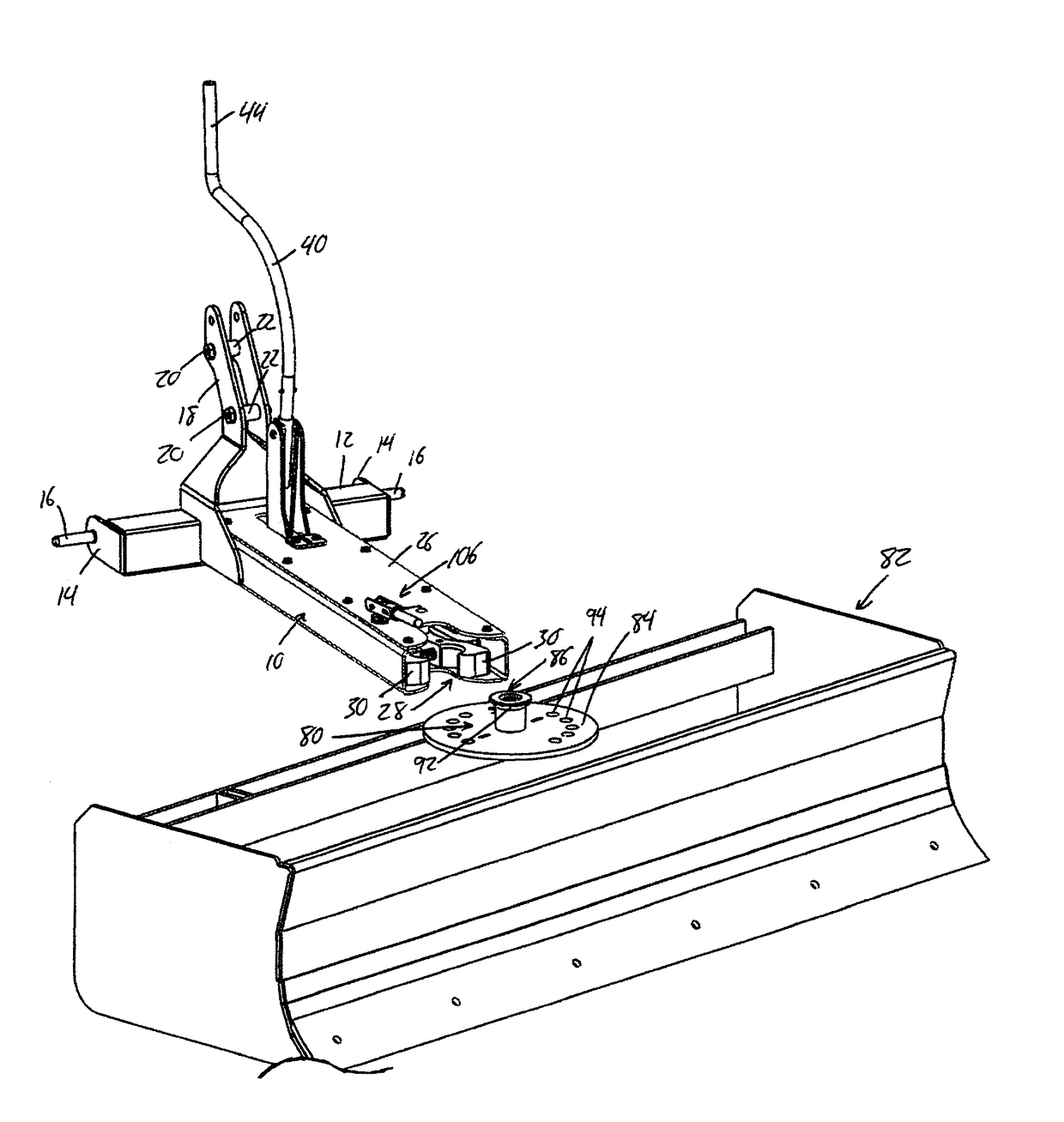
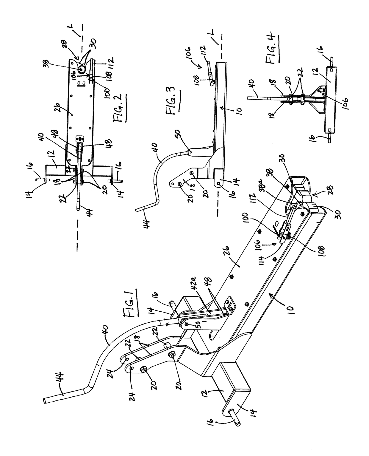
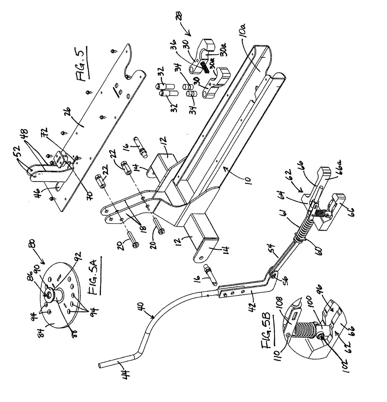
[0054]FIG. 1 illustrates a hitch conversion unit according to one embodiment of the present invention. The unit features an elongated housing 10 having opposing front and rear ends spaced apart along a longitudinal axis L. A cross member 12, for example in the form of a length of rectangular tubing, spans perpendicularly across the elongated housing 10 at the front end thereof to reach laterally outward to both sides thereof. At each end of the cross member 12, a respective lug 14 juts forwardly therefrom, and a respective mounting pin 16 juts laterally outward from the lug in parallel relation to the cross member 12. A pair of uprights 18 stand upwardly from the front end of the elongated housing. Upper portions of the uprights stand in parallel relation to one another at a spaced apart distance maintained by two sets of bolts 20 and spacers 22 that horizontally fasten the uprights together above the elongated housing. A pair of aligned holes 24 in the upper portions of the upright...


PUM


Abstract

A conversion unit is used for indirect attachment of a mounted implement to a working machine. The mounted implement features a single-point connector, while the conversion unit features both a multi-point mounting arrangement configured for removable coupling to a multi-point attachment arrangement on the working machine, and a single-point coupler configured for removable coupling to the single-point connector of the mounted implement. With the conversion unit in an operating position attached to the attachment arrangement of the working machine, coupling of the mounted implement to the conversion unit via engagement of the single-point coupler with the single-point connector indirectly attaches the mounted implement to the working machine in a mounted position thereon. A shared upright axis of the single-point coupler and single-point connector allows angular adjustment or free-swiveling of the implement about the shared axis when a corresponding lock pin is withdrawn from locking position that blocks such movement.

Description

CROSS-REFERENCE TO RELATED APPLICATIONS[0001]This application claims benefit under 35 U.S.C. 119(e) of U.S. Provisional Application No. 62 / 444,057, filed Jan. 9, 2017, the entirety of which is incorporated herein by reference.FIELD OF THE INVENTION[0002]The present invention relates generally to mounting of implements to tractors and other working machines.BACKGROUND[0003]In the field of agricultural machinery, different categories of machine are characterized by the manner in which they are supported and conveyed over the ground. Implements that rely on a tractor as a source of propulsion are divided into three general categories, namely mounted implements, semi-mounted implements and trailed implements. A mounted implement refers to an implement that is supported entirely by the tractor, typically by way of a three-point hitch found thereon, when the implement is in a raised or transport position in which the earth-working tools of the implement are raised out of engagement with t...

Claims


Application Information

Patent Timeline
IPC IPC(8): A01B59/00A01B59/06A01B63/02
CPCA01B59/002A01B59/066A01B63/02A01B59/062A01B59/063
Inventor LOEWEN, JONATHAN S.
Owner MOTOALLIANCE INC
Why Eureka
Try Eureka