Expandable spinal interbody cage

a spinal interbody cage and expandable technology, applied in the field of expandable spinal interbody cages, can solve the problems of affecting the stability of the spinal interbody cage, and limiting the attempt to minimize the wound size, so as to achieve smooth and steady movement, increase or decrease the height of the spinal interbody cage, and facilitate the effect of implantation

Active Publication Date: 2018-07-12
KE LING BIOTECH LTD
View PDF1 Cites 25 Cited by
  • Summary
  • Abstract
  • Description
  • Claims
  • Application Information

AI Technical Summary

Benefits of technology

[0019]By means of the spinal interbody cage of the subject invention, the height of the spinal interbody cage can be increased or decreased continuously, smoothly and steadily by rotating the screw arbor so as to match the height between the spines of a patient, providing more stable support. Moreover, during the process of adjusting the height of the spinal interbody cage, the screw arbor and the slide block will not exceed the upper plate or the lower plate in the direction of t...

Problems solved by technology

When any sections of the intervertebral disk change pathologically or due to aging, pain will occur due to compression of the adjacent spinal nerve, resulting in impaired movement.
However, the height of the conventional spinal interbody cage is fixed and thus constrains any attempt to minimize wound size.
When the spinal inte...

Method used


Image

  • Expandable spinal interbody cage
  • Expandable spinal interbody cage
  • Expandable spinal interbody cage

Examples


Embodiment Construction

[0027]Following are the detailed descriptions of the embodiments of the subject invention with reference to the drawings. It should be noted that the content of the embodiments only serves to show the practical configuration of the subject invention and does not impose any limitation on the scope of the claimed invention.

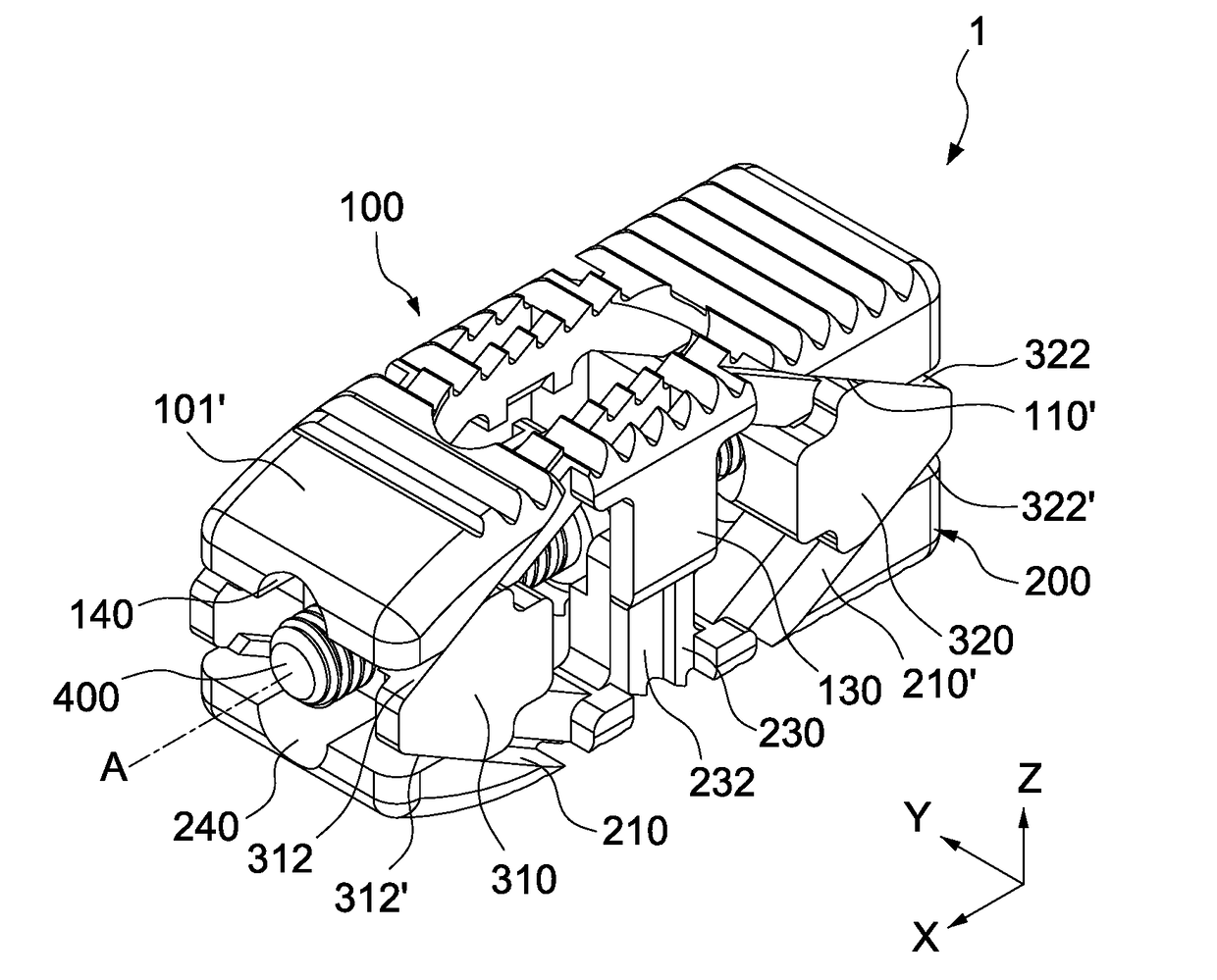
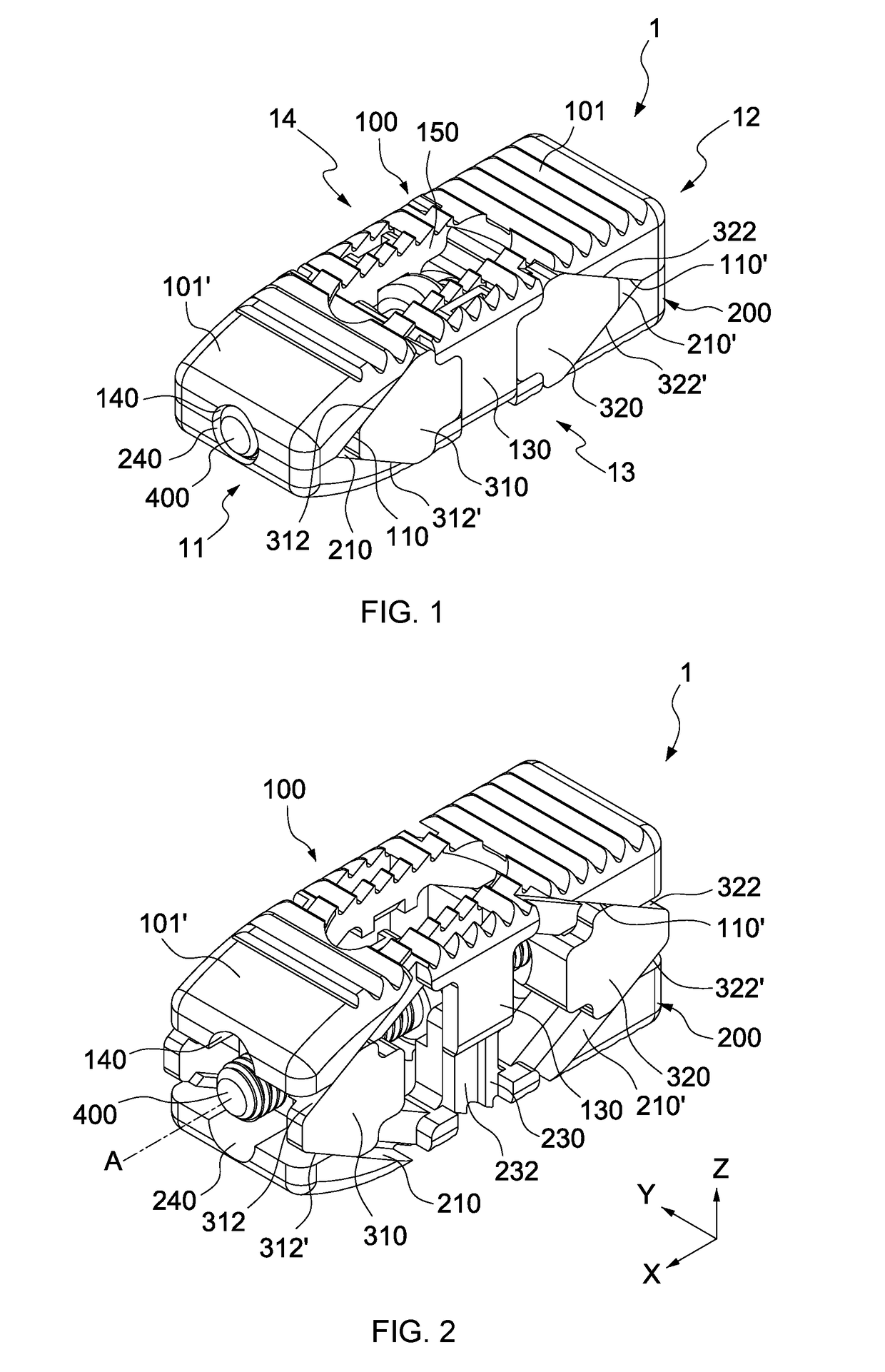
[0028]Firstly, refer to FIG. 1 and FIG. 2, which disclose the perspective view of the spinal interbody cage 1 under the state of the minimum height and being expanded in one embodiment of the subject invention. In order to clearly describe the embodiment of the subject invention, the direction of the long axis X, lateral direction Y and vertical direction Z are defined.

[0029]As shown in the figures, the spinal interbody cage 1 comprises a first end 11, a second end 12, a first side 13 and a second side 14, wherein the first end 11 and the second end 12 are opposite each other in the direction of the long axis X of the spinal interbody cage 1, the first side 13 and t...


PUM


Abstract

Disclosed herein is a spinal interbody cage, comprising an upper plate, a lower plate, a screw arbor and two slide blocks. The screw arbor includes a first section with an outer thread and a second section with an outer thread. The outer threads of the first and second sections have opposite directions. The upper plate respectively has a pair of upper plate slanted surfaces proximate to the first and second sections of the screw rod. The lower plate respectively has a pair of lower plate slanted surfaces proximate to the first and second sections. The screw rod is disposed in and cooperates with the inner threads of the slide blocks. The screw rod and slide blocks are arranged between the upper and lower plates. The slide blocks respectively have two slide block slanted surfaces, each abutting and cooperating with one of the upper and lower plate slanted surfaces so as to distance the upper plate from the lower plate when the slide blocks are distanced from each other by rotating the screw rod in one direction.

Description

CROSS-REFERENCE TO RELATED APPLICATION[0001]This application claims the benefit of the filing date of Republic of China Patent Application No. 106100530, filed Jan. 6, 2017, this application also claims the benefit of the filing date of Republic of China Patent Application No. 106122785, filed Jul. 7, 2017, the disclosure of each of which is hereby incorporated herein in its entirety by this reference.TECHNICAL FIELD[0002]The present invention relates to an interbody cage. Specifically, the present invention relates to an expandable interbody cage.BACKGROUND[0003]The human spine is composed of several vertebrae and an intervertebral disk. The intervertebral disk is a tissue containing a large amount of water and can absorb the vertical pressure of the spine and provide cushioning effect between upper and lower vertebrae. When any sections of the intervertebral disk change pathologically or due to aging, pain will occur due to compression of the adjacent spinal nerve, resulting in im...

Claims


Application Information

Patent Timeline
IPC IPC(8): A61F2/44A61F2/30
CPCA61F2/447A61F2/30771A61F2002/30143A61F2002/30537A61F2002/30828A61F2002/30553A61F2002/30579A61F2002/30413A61F2002/304A61F2002/4475A61F2002/30775A61F2002/30006A61F2002/30904A61F2/4455A61F2002/30538
Inventor HSU, SHAO-KEHLIN, CHIEN-YUTSENG, KUO-WEI
Owner KE LING BIOTECH LTD
Why Eureka
Try Eureka